™ MAXIMTM III CLASSROOM AUDIO SYSTEM INSTALLER AND OPERATIONS MANUAL Amplifier Audio Mixer Infrared Microphone Receiver P/N UMM-500
Maxim III introduction thank you Congratulations on the purchase of your new TeachLogic system. You can be assured that this ffulfills all specifications and was produced to very high quality control standards. TeachLogic incorporates the latest state of the art technology, employs the most advanced manufacturing methodology and uses only premium quality components to assure many years of reliable performance. We appreciate your confidence by your selection of our product.
safety instructions Read Instructions All safety and operation instructions should be read before operating this TeachLogic product. Retain Instructions Safety and operating instructions should be kept for future reference. certifications Water & Moisture This product should not be operated near water. Heat Environment Do not subject this product to excessive heat conditions. TeachLogic systems are manufactured using leadfree processes and are free of materials harmful to the environment.
Maxim III system info Date of Purchase: Model Number: Serial Number: Notes: contact 5-year limited warranty If you should encounter some unresolved issue, please contact the TeachLogic customer service department for further assistance. For full warranty details refer to: www.teachlogic.com/warranty 1•760 • 631•7800 support@teachlogic.com teachlogic.
table of contents System Overview .................................................... 1 System Diagram ...................................................... 3 Installation 5 Installation Planning............................................... 5 Installation of Ceiling Sensor ............................... 6 Installation of Speakers ......................................... 7 Integration 9 Page Mute/Pass Through Integration .............. 9 Fire Alarm Input ................................
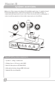
Maxim III system overview Make note of the components planned for installation and setup. A complete Sound Field system will have the components shown below. The quantity and type of components will vary based on your order. Please check your invoice, packing slip, or contact us with any questions about what components you should have. 1 3 2 4 5 Sound Field system components 1. Speakers - ceiling or wall mount 2. Ceiling Sensor + 50' sensor cable (RCA) 3. Wireless Microphones (IRT-60 & IRH35) 4.
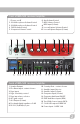
front of IMA-520 receiver/amplifier 1 2 3 4 5 Power on/off CH A Microphone Volume Control CH B Microphone Volume Control DVD Volume Control Computer Volume Control 1 2 1 3 2 3 4 4 5 6 7 8 6 7 8 9 10 5 9 Aux Volume Control MP3 Volume Control MP3 Input (3.5mm) Lesson Capture Volume Control Lesson Capture Output (3.
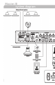
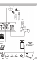
Maxim III system diagram owner’s man owner’s man note 3
nual nual 4
Maxim III installation v installation planning 1. Amplifer/Receiver: Choose location the based on accessibility requirements and wiring constraints for power, speakers, and audio devices. Ceiling Sensor: Centrally locate on ceiling; maintain line of sight; keep away from direct light and electrical interference. Speakers: Mark location for wall mount vs. ceiling mount, and confirm wiring run to the amplifier. Ensure speakers evenly cover the listening area.
product description installation of ICS-55 ceiling sensor The ideal location for the ceiling sensor is in the center of the room's ceiling. The ideal installation is flush mounted on a white, reflective ceiling like the acoustic drop-down style. This will ensure 360º coverage and will minimize the transmission distance for more reliable performance. power “on” LED Green light indicates that the sensor is receiving power from the receiver.
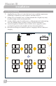
Maxim III installation installation of speakers The IMA-520 (and IMA-524) has two channels of amplified audio, rated for a minimum 4-ohm speaker load. There are two blue Phoenix style speaker connectors on the back panel, each providing two pairs of speaker terminals. The top connector provides connection to both channels as does the bottom connector. Each is wired in parallel to the other as shown below. These are the acceptable wiring methods.
SP-628 ceiling speakers SP-2000 wall mount speakers 1. Determine the listening area. 2. Divide listening area into quadrants 3. Locate and identify the center most tile in each quadrant 4. Lay ceiling tile face down on clean flat surface 5. Lay tile bridge on ceiling tile and center it 6. Trace and cut the large hole 7. Strip the speaker cable ends, approx. ½" 8. Route speaker wire from speaker opening to amplifier 9. Reinstall ceiling tile with tile bridge in place above the hole 10.
Maxim III integration transmitter page mute/page pass through Effective for shipments after 4/1/19 of new units; serial numbers beginning with A19 and later (letter or number is A, B, C… and number is 19, 20, …). For older units see notes at the end of this section. New units: A paging system may be connected to the Maxim III. The panel labeling is based on a 25-volt paging input signal. The Page Input impedance switch has three labeled positions (based on power draw at 25V): • 0.1W DRAW • 1.
New Models: Switch Setting: 0.1W DRAW 1W DRAW MUTE OFF 5000Ω 620Ω Open circuit Power Draw at 25V 0.1W 1.0W 0W Power Draw at 70V 1.0W 7.9W 0W 100V 70V 25V 5000Ω 620Ω 115Ω Power Draw at 25V 0.1W 1.0W 5.3W Power Draw at 70V 1.0W 7.9W 42W Impedance Older Models: Switch Setting: Impedance Connecting the system: 1. 2. 3. 4. 5. 6. 7. 8.
Maxim III integration transmitter RS-232 feature The RS-232 feature allows the user to remotely operate the line level media inputs via a convenient wall panel controller. Audio levels very often need to be adjusted when switching from computer audio to DVD players and other audio sources. Such operations as level UP, DOWN and MUTE are easily accomplished via a typical eight button controller, as shown here.
RE-232 and Security Alert contacts security alert feature Effective for shipments after this date of new or reprogrammed units. Serial numbers beginning with A19 and later (letter or number is A, B, C… and number is 19, 20, …). The Maxim III security alert feature, when triggered by an IRT-60 sapphire mic on Channel A, creates a relay contact closure or opening. The back panel connection is a normally closed and normally open terminal paired with the common terminal.
Maxim III integration security alert features To check the mode Note the LED color on the power button at the TL logo. If power state is ON (Blue LED at power button), press once to set power state OFF (Red LED). • If Red, then you may start the process. • 1. 2. 3. Press and hold the power button (in Red state) for the entire process. After 4 seconds, the LED will change colors. Note the number of RED flashes AFTER the GREEN flash. If one RED after GREEN, then mode is 1-pulse mode.
Power button RS-232 switch security alert activation test 1. Ensure the amplifier is powered on and a solid 2. 3. 4. 5. 6. blue light appears on the power button. Ensure the ceiling sensor is attached to the amplifier. The sensor's green LED should be illuminated. Power on the IRT-60 Sapphire microphone that uses Ch. A. The power button should be solid blue. While watching the amplifier power button, press and hold the IRT-60 PRIORITY button for 4-5 seconds.
Maxim III Configuration transmitter initial setup Now that the system is installed and connected, turn the system “ON” and test its performance. The testing will be done using an IR transmitter (Sapphire or Handheld) to confirm good connectivity. system operation AMPLIFIER • Turn the Maxim III on by pushing the power button. A solid blue LED indicates amplifier is powered ON.
troubleshooting Problem Solution System is turned “on” but there is no sound • Verify AC power; the Blue LED lights when turned “on” • Check if system has been unplugged • Check circuit breaker • Call maintenance for assistance System has power but no sound • Turn “on” microphone/ transmitter • Ensure the power light is on (colors indicate charge level) RED: Low battery BLUE: full battery Note: blinking blue means it has been muted. Press once to unmute.
Maxim III Specifications transmitter Maxim III (IMA-520) specs. Receiver Input Modulation Reception Frequencies Infrared Wavelength Pilot Signal De-emphasis Frequency Response S/N Ratio THD Nominal Deviation Maximum Deviation External Sensor Input Aux Inputs Speaker Impedance Output Connection Power Supply Infrared FM FM Wide-band Ch. A: 2.08 MHz | Ch. B: 2.54 MHz 850 nm 32.
Sapphire transmitter (IRT-60) specs. Transmitting Diodes Operating Range Battery Discharge Indicator Blue Purple Red Flashing Red Battery Used Battery Life External Power Charger Transmission Angle User Controls Power Switch (push) Mute Switch (push) Mic Switch (3 position) Aux. Vol./Gain Priority Security Alert External Aux. Input Dimensions Weight Six 60 Ft. Line of Sight Full Medium Low Very Low Battery Lithium-ion (3.7V / 620mAh) Approx.
1-760 - 631-7800 support@teachlogic.com teachlogic.