owner’s manual Infrared Wireless Microphone System
VoiceLink I owner’s manual
notes Date of Purchase: Model Number: Serial Number: Notes:
VoiceLink I owner’s manual thank you Congratulations on the purchase of your new VoiceLink I Infrared Wireless Microphone Sound System. You can be assured that the VoiceLink I fulfills all specifications and was produced to very high quality control standards. TeachLogic incorporates the latest state of the art technology, employs the most advanced manufacturing methodology and uses only premium quality components to assure many years of reliable performance.
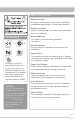
safety instructions Read Instructions All safety and operation instructions should be read before operating this TeachLogic product. Retain Instructions Safety and operating instructions should be kept for future reference. certifications US CA Listed Water & Moisture This product should not be operated near water. Heat Environment Do not subject this product to excessive heat conditions.
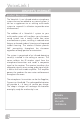
VoiceLink I owner’s transmitter manual table of contents About Infrared ............................................................. 1 Product Description ................................................... 2 VoiceLink I System .................................................... 3 Microphone/Transmitters ...................................... 4-5 Drop-in Chargers / Ceiling Sensor ......................... 6 Installation of System ................................................
a brief word about infrared IR transmission The IR transmitter transmits directly to the sensor. However; due to the strength of the IR transmitter, the infrared signal will bounce off the walls, ceiling and floor for reception thus providing continuous connectivity throughout the room. Benefit: total freedom of movement within the room with no restriction of orientation. “What’s said in the room, stays in the room”.
VoiceLink I owner’s manual product description The VoiceLink I is an infrared wireless microphone system that can be added to any sound system. It can be a supplement to an existing multi-media system to expand it's utilization to provide voice reinforcement.
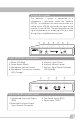
VoiceLink I system The VoiceLink I system is comprised of a microphone / transmitter, either the Sapphire (IRT-55), or Handheld ( for voice transmission to a ceiling sensor (ICS-55) that sends the signal to the receiver / mixer (IR-100). The receiver processes the signal and produces an analog signal of your voice for input to an amplified sound system. 1 2 3 4 5 CH A 6 7 AUX IN POWER front of IR-100 receiver/mixer 1 2 3 4 5 Auxiliary Input (3.
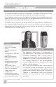
VoiceLink I owner’s manual infrared microphone/transmitters The infrared microphone/transmitter is comprised of a microphone input, signal processing circuits and several emitting diodes that transmit the vocal signal to the sensor. The microphone/transmitter can be the Sapphire or Handheld. The rechargeable batteries will provide 6–8 hours of service per charge. Place the microphone/transmitter in the charger for overnight charge and it will be ready for another day’s use.
features • Condenser microphone element • Power “on/off ” switch • Battery level indicator— LED • Channel “A” or “B” selectable • 10 high-power emitting diodes • Diodes at top and bottom of handle for increased Coverage (2 Top aimed out, 6 Bottom 360°, 2 Bottom aimed down) • 360º IR radiation for assured connectivity • Two “AA”, Duracell, rechargeable NiMH batteries IRH-35 handheld transmitter The Handheld Microphone Transmitter (IRH35) is most applicable for student use or direct presentation.
VoiceLink I owner’s manual BRC-55 drop-in battery charger This stylish desktop drop-in charging station makes it convenient and easy to recharge both Sapphire Pendant and Handheld Microphones. Charge one IRH-35 handheld transmitter and up to two IRT-55 Sapphire transmitters simultaneously. Charging indicator lights illuminate Red when charging, and Green when fully charged. The “TL” logo illuminates Blue when plugged in.
installation of system Location of receiver is primarily determined by user accessibility, location of sound system and availability of an electrical outlet. Location of the sensor and routing of the sensor cable is a more critical issue. location and Installation of receiver Since the VoiceLink I is a supplement to an existing power amplifier system, you will want to locate the receiver near the power amplifier to minimize audio cable length from receiver to sound system.
VoiceLink I owner’s manual installation of ICS-55 ceiling sensor The ideal location for the ceiling sensor is in the center of the ceiling. This will provide a clear signal path for the IR transmission from the transmitter to the dome sensor without obstruction. In addition, you will have 360º coverage and will minimize the transmission distance for more reliable performance.
operation of VoiceLink III system Now that the system is installed and connected, we are ready to turn the system “ON” and test its performance. The testing will be done using an IR transmitter (Sapphire or Handheld) to confirm good connectivity and quality audio.
VoiceLink I owner’s manual projector system setup Ceiling Sensor Speakers How to Interface VoiceLink I with a Video Projector and incorporate the Projector’s Remote Control Infrared Transmitter “Sapphire” IRT-55 • With the corner sensor installed, connect it to VoiceLink I • Locate VoiceLink I near projector and connect to AC power • Connect an audio cable with 3.
Speakers INPUT Rear View of VoiceLink I Power Amp (Not Supplied) INFRARED MIC AUX IN POWER VoiceLink I Front View AUDIO IN 1 AUDIO IN 2 AUDIO IN 3 SENSOR Video Projector DVD Player Computer MP3 Player Two sensors may be placed at opposite (diagonal) corners for additional coverage.
VoiceLink I owner’s manual troubleshooting Problem Solution System is turned “on” but there is no sound • Verify AC power; the Red LED lights when turned “on” • Check if system has been unplugged • Check circuit breaker • Call maintenance for assistance System has power but no sound • Turn “on” microphone/ transmitter • Check for IR transmission, Signal presence (Orange LED) • Check the Yellow LED in the sensor • If sensor LED is not lit • Sensor has been disconnected • Power output to sensor h
blank page 137
VoiceLink I owner’s manual VoiceLink I (IR-100) specs. Receiver Input Modulation Reception Frequencies Infrared Wavelength Tone Signal De-emphasis Frequency Response S/N Ratio THD Nominal Deviation Maximum Deviation External Sensor Input Aux Input Line Output Power Supply Dimensions Weight Enclosure Infrared FM FM Wide-band Ch. A: 2.08 MHz 850 nm Ch. A: 32.768 KHz 50 µs 50 Hz, -13KHz, ± 3dB ›65 dB ‹1% @1KHz ± 10 KHz ± 25 KHz Two, RCA 3.
Sapphire transmitter (IRT-55) specs. Transmitting Diodes 6 Operating Range 1,600 Ft ². 60 Ft. Line of Sight Battery Discharge Indicator Blue Full Purple Medium Red Low Flashing Red Very Low Battery Battery Used Lithium-ion (3.7V / 620mAh) Battery Life Approx. 8-9 Hrs/Charge External Power Charger DC +5V, Micro USB Connector Transmission Angle Conical User Controls Power Switch (push) On/Off Mute Switch (push) On/Off Mic Switch (3 position) +6db, Normal, -3db Aux. Vol.
VoiceLink I five year limited warranty TeachLogic IR products are guaranteed to be free of defects in workmanship or material for a period of five (5) years from date of original purchase, subject to the following conditions: 1. Warranty excludes defects caused by normal use and wear, any abuse, or failure to use the product in accordance per instructions. 2. Warranty is void if damage occurred because of misuse, or attempted repair or modification by unauthorized personnel. 3.
17
1688 Ord Way Oceanside, CA 92056 1•800 •588• 0018 sales@teachlogic.com 1•760 • 631•1283 www.teachlogic.