
LED Kit Instructions

#29266 XP LED RC Light Kit (12pcs)
User Manual
Thank you for your purchase of a new Team Associated LED light kit. This powerful and easy to install light kit is the first choice for
most model car enthusiasts. The kit provides a variety of unique features, and it’s recommended that you read the instructions carefully
prior to installation and use. Improper installation may result in damage to the product.
[Product Features]
Intelligent operating system with a variety of possible applications
Led system connects to your current radio system without the use of an auxiliary channel
The system provides eight different light operating modes; Normal operating mode, night mode, fog mode, emergency mode
and four different burst flash modes.
[Product List]
LED system control box
Servo extension cable x 2
Setup/operating manual
Programming switch
LED light strands:
5mm white LED x 4
5mm red LED x 2
3mm yellow LED x 4
5mm Blue LED x 2
[Installation]
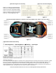
1.) Lay out the lights to the desired section of the body. (refer to Figure 3)
2.) Use a body reamer to make the holes for the LED light grommet. (be careful to not make hole too large)
3.) Install Grommets into the body, followed by the light into the grommet.
4.) We recommend routing the wires so that they are clear from the antenna wire. This will prevent any interference to the radio.
5.) Using a piece of double sided tape, mount the control box to the desired location on the body.
6.) Plug Light strands into corresponding sockets on the control box. (refer to figure 1)
7.) There are two servo wire ports on the control box for each Channel. Using one pair of the ports, (Ch.1 and Ch.2) Use the
servo extension cables to connect your receiver to the control box. You will match Ch. 1 on the control box to Ch. 1 on the
receiver. Same will go for Ch. 2. (refer to figure 2)
8.) In the other pair of servo wire sockets on the control box, connect your Servo (Ch. 1) to the Ch. 1 port. Next, connect your
speed control to the Ch. 2 port. (refer to figure 2)
9.) Lastly, install the programming switch into the port between sockets 5/6 and 7/8. Make sure that the black wire is pointed away
from the Ch. 1 and Ch. 2 ports.
* If the “left” and “right” turn lights are reversed, simply change the side of the car that the light is on.
[Function Control]
When the car is turned on, all LEDs will come on for 1 second. When full throttle is applied, the lights will flash twice indicating that the
light kit is ready for use. The default setting is “normal operating mode.” In this mode, the lights will work as on a real car. There are
eight different light modes to choose from; Normal operating mode, night mode, fog mode, emergency mode and four different burst
flash modes.
To change different light modes:
Use the Programming switch to change through the different modes. Each time the button is pressed, it will change to the next mode in
order of how they are listed above. Once the desired light mode is reached, simply stop pressing the button and it will stay on that
mode. (Remember, if the car is turned off, the control box defaults to the “normal operating mode”)
[Product Parameters]
Operating voltage: 4.8v-6.0v
Operating current: 100mA
Dimensions of control box: 89 x 32 x 16mm
LED cable Length: 430mm
Servo extension cable length: 320mm
Weight: 50g