:: Introduction Thank you for purchasing this Team Associated Qualifier Series product. This manual contains instructions and tips for maintaining your new Pro Rally RTR. Please take a moment to read through it and familiarize yourself with these steps as they will help you to understand each component’s function and show you some tips for getting the most out of your Pro Rally RTR.
4/14 :: Table of Contents 1....................Cover 11-13..........Spur Gear / Rear Diff Access 2....................Introduction 13-14..........Front Diff Access 3....................Table of Contents 14.................Diff Maintenance 4....................Blueprint of a Pro Rally 4x4 14-15..........Shock Maintenance 5-7................Quick Start Guide 16.................Motor Manual 8....................Radio, Speed Control Wiring 17................. ESC Manual 9...................
:: Blueprint of a Pro Rally Front Bumper Front Arm Turnbuckle (Front Camber Link) Front CVA Front Shock Caster Block Steering Block Front Body Mount Front Shock Tower Turnbuckle (Front Steering Link) Chassis Turnbuckle (Front Servo Link) Battery w/ Deans® Plug Receiver Box Nerf Bar Drive Shaft Electronic Speed Control Battery Strap Motor Slipper Clutch Pinion Spur Gear Rear Arm Rear Shock Tower Rear Hub Rear Dogbone Rear Diffuser Rear Shock Rear Body Mount Turnbuckle (Rear Camber Li
:: Quick Start Guide Battery Charging Steps and Safety: NiMH Wall Charger: (Part #29154 Wall Charger AC 120V 350MaH) NiMH Quick Charger: (Part #610 Reedy 447-S AC/DC 4-7 Cell Peak Prediction NiMH/NiCd Charger) Remove the battery from the vehicle before charging. Be sure to select the correct charging mode for the type of battery you are charging. NEVER leave the battery unattended while charging! NiMH: NiMH batteries (nickel-metal hydride) are high current rechargeable batteries.
:: Quick Start Guide - (cont.) Change the speed control to NiMH or LiPo battery modes. *NOTE: The Transmitter & ESC come Pre-Programmed! 1) 2) 3) 4) 5) 6) 7) 1 Make sure both TH. ATV (LO & HI) is set on your transmitter all the way to the right or at 100% before you start. Turn on the transmitter. Pull trigger to full throttle and hold it. Turn on the speed control. You will hear six beeps (bibibibibibi) and see six flashing green lights. Release trigger back to neutral.
:: Quick Start Guide - (cont.) Radio System Tuning and Controls: 4 RULE: Transmitter on First/Vehicle on Second, Vehicle off First/ Transmitter off Last! 1) 2) 3) 4) Slide the battery cover in the direction shown to remove cover. Install six (6) alkaline or rechargeable AA size batteries into the battery holder. Slide the battery cover back into place making sure it is completely closed and secore. Turn the power ON.
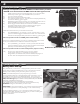
:: Wiring Diagrams Receiver Box Gasket Maintenance: 1. Apply a small amount of “hobby grade” glue (not included) to the top edge of the receiver box in order to hold the receiver box gasket in place. Do the same for the receiver box lid. Make sure not to get glue on the side of the gaskets that will make contact with each other! Wait untill the glue has completely dried before moving on to the next step! 2.
:: Gear Mesh Gear Mesh: To correctly set your gear mesh, follow the steps below: 1. Remove the Chassis Brace. Loosen the set screw on the motor’s pinion gear. Slide the pinion on the motor shaft until the gear face of the pinion is entirely aligned with the gear face of the spur gear (see diagram). Tighten the set screw while ensuring it is aligned with the flat face on the motor shaft. Pinion Spur Gear 2. Loosen the motor clamp screw until the motor is able to move freely.
:: Camber / Toe Front Camber Angle: A good starting camber setting is –2 degrees (where the top of the tires lean inwards). Positive camber, where the top of the tire is leaning out, is typically not recommended. Front Toe-In: Zero degree toe-in (tires pointing straight forward) is a good starting setting. You can increase steering into corners by adding 1-2 degrees of toe-out (front of tires point slightly outward). Front toe - in is not a typical tuning adjustment used.
:: Bumper Adjustments Bumper Adjustments: On-Road To run your vehicle in off-road conditions (big jumps), it is recommended that you switch your front and rear bumpers to their off-road positions. This allows for greater ground clearance. The body should be trimmed level with the bottom edge of the bumper. Front Bumper Adjustments: Off-Road :: Bumper Adjustments - (cont.) Rear Bumper Adjustment: On-Road ! Remove and flip brace over.
:: Spur Gear Access - (cont.) Rear Shock Tower Removal: Loosen the ball studs highlighted in order to remove the shock tower with the shocks and camber turnbuckles attached as one completepiece. The dogbones will come out when the shock tower is removed. Make sure you replace them when re-installing the rear shock tower! :: Spur Gear Access - (cont.) Slide center bulkhead cap forward to remove slipper assembly! :: Spur Gear Access - (cont.
:: Spur Gear Access - (cont.) Spur Gear Maintenance: When accessing your spur gear, check for wear on the teeth of the gear. The teeth should be nice and sharp. Also, check the slipper pads for wear. Replace if necessary. A good starting point for slipper setup is to have 3.5 to 4.0mm of thread showing on the shaft. 3.5mm-4.0mm of thread showing Slipper Pads :: Front Diff Access - (cont.) :: Front Diff Access - (cont.
:: Front Diff Access - (cont.) :: Diff Maintenance Differential Maintenance: Once you have removed the Diff gear, you can now drain the existing diff fluid from the differential. Stock Diff Fluid Setting: Check the diff gasket for wear or damage. Replace if necessary Front: black grease Fill the diff to the top of the cross pin with your choice of black grease #6588 or diff fluids.
:: Shock Maintenance - (cont.) Bladder Installation 3 Sho 5wt ck f lui d Stock Shock Fluid Setting: Front: 35wt Rear: 35wt A B C As you install the shock cap with the bladder, it will force out any extra fluid. If you install the cap with the shaft fully extended, you are running FULL REBOUND.This means the shaft will fully rebound when compressed. To run less rebound, unthread the cap 1-2 turns and compress the shaft to the desired position and re-tighten the cap with the shaft compressed.
:: Motor Manual 550-SL BRUSHLESS MOTOR Introduction Caution Congratulations on your purchase of the Reedy 550-SL Brushless Motor. The latest brushless motor technology along with the design and engineering experience that is responsible for 29 World Championship titles has been incorporated into its design. When switching to a higher voltage battery from a lower one (11.1V to 7.4V, for example), a change in gear ratio or a lower kV motor might be necessary.
:: ESC Manual
:: Shocks 4187 5407 7143 7144 7145 7146 7147 7148 7149 7150 7151 7152 7725 25231 :: Servo Saver/Mount Nylon Spacer .030 Red Silicone O-Ring Rear Shock Kit Front Shock Kit Shock Bodies, FR/RR w/ Top & Bottom Caps, & Hat Bushings Shock Bladders Shock Shafts, FR/RR w/Rod Ends (4) Pistons, 1.2, 1.3, 1.4 w/E-Clips Shock Clips w/Spring Retainer (4), Spring Cup (4), & Rod Ends (4) Shock Springs, Soft FR/RR Shock Springs, Medium FR/RR - Kit Shock Springs, Hard FR/RR Fuel Tubing 3 feet E-Clip, 2.
:: Front and Rear Gear Differential 7133 7134 7189 7732 25607 31350 1 2 1 6 4 6 Diff - Complete Diff Outdrive w/Set Screw Diff Rebuild Kit M4 x 4mm Set Screw Bearing, 8 x 14 x 4 M2.5 x 10mm FHCS 25607 7134 7134 -OR7732 7189 31350 7189 25607 7134 7134 -OR7732 :: Battery Strap :: Lubes & Adhesives / Decals / Misc.
:: Front Gearbox 2308 5407 7116 7117 7124 7134 7135 7155 7158 7163 7166 7732 25202 25211 25215 25231 25710 89202 M3x18mm BHCS Red Silicone O-Ring ProLite Chassis Braces Gearboxes FR/RR, Top & Bottom Front Input Shaft, Set Diff Outdrive, w/ set screw Drive Pinion Arm Mounts, A & D Plates Hinge Pins (inner & outer), Bushings (0, 1, 2, & arm washers) Set Ball Stud, (3 short/7 long) Set 4mm E-Clip M4x4mm Set Screw M3x10mm FHCS M3x10mm BHCS M3 Locknut, black E-Clip, 2.
:: Rear Gearbox 7117 7155 7158 7163 25202 25215 89202 1ea 1ea 1 Gearboxes FR/RR, Top & Bottom Arm Mounts, A & D Plates Hinge Pins (inner & outer), Bushings (0, 1, 2, & arm washers) Set Ball Stud, (3 short/7 long) Set M3 x 10mm FHCS M3 Locknut, Black M3 x 12mm BHCS 89202 1 20 20 10 7163 89202 7163 7117 7158 7158 7158 7158 7158 7158 25215 7158 7158 7155 7117 7158 7158 25202 :: Rear Suspension 7131 7132 7142 7156 7163 7158 7165 7168 25616 91027 91148 Dogbone (RR) Axle/Dogbone Hub Carrier Rear
:: Front Bumper 2308 7171 7188 25201 89202 89204 M3 x 18mm BHCS Pro Rally Foam Bumper Pro Rally Bumper Set M3 x 8mm FHCS M3 x 12mm BHCS M3 x 24mm BHCS 6 1 1 20 10 10 2308 7188 89202 2308 89202 7171 -OR7188 89202 7188 89204 7188 7188 25201 89204 :: Rear Bumper 2308 7172 25201 91478 M3 x 18mm BHCS Pro Rally Diffuser Set M3 x 8mm FHCS M3 x 30mm BHCS 6 1 20 6 91478 7172 2308 7172 25201
:: Front Shock Tower 7153 7154 7173 7184 25187 25215 89205 89218 :: Rear Shock Tower Shock Bushings Shock Tower, Front & Rear Pro Rally Body Mount Set M2 x 16mm SHCS M3 x 14mm BHCS M3 Locknut, Black M3 x 26mm BHCS Washer, 3 x 8mm 4 1ea 1 10 20 20 10 10 7153 7154 7173 7184 25187 25215 89205 89218 Shock Bushings Shock Tower, Front & Rear Pro Rally Body Mount Set M2 x 16mm SHCS M3 x 14mm BHCS M3 Locknut, Black M3 x 26mm BHCS Washer, 3 x 8mm 4 1ea 1 10 20 20 10 10 7173 7173 7173 7184 7173 7173 718
:: Chassis 2308 7112 7113 7114 7116 25187 25202 25211 25215 31532 89202 89203 M3x18mm BHCS ProLite Chassis Nerf Bars Receiver Box w/Gaskets ProLite Chassis Braces M3x14mm BHCS M3x10mm FHCS M3x10mm BHCS M3 Locknut, black M3x8mm BHCS M3x12mm BHCS M3x16mm BHCS 6 1 2 1 1 20 20 20 20 6 10 10 2308 25211 25187 25211 31532 89203 31532 7114 25187 31532 7116 89202 7114 7116 7116 7114 7113 25215 89202 25215 7112 25202 89202 25215 89202 7113 25202 25215
:: Slipper, Spur Gear, Pinion, and Drive Shaft 5407 7122 7123 7124 7125 7126 7127 7135 7732 25225 25231 25710 91162 91163 91164 91165 91166 Red Silicone O-Ring Spur Gear 32P, 47T Slipper Hardware, Kit Slipper Shaft Slipper Pads Slipper Hubs Drive Shaft w/ O-Rings Drive Pinion M4x4mm Set Screw M3x3mm Set Screw E-Clip, 2.
:: Body / Wing / Decals 6332 7179 7180 7181 7182 7187 89202 :: Factory Team and Option Parts Body Clips Pro Rally Wing Set Pro Rally Body, Clear (wing not included) Pro Rally Rockstar Body, Black Pro Rally Rockstar Body, White Pro Rally Decal Sheet M3x12mm BHCS 6 1 1 1 1 1 10 1734 1735 1736 1737 7183 9787 31286 31550 91160 91171 FT Body Clips, Metallic Blue, 4 Long, 6 Short FT Body Clips, Metallic Blue, Long FT Body Clips, Metallic Blue, Short FT Body Scissors Sway Bar Set - Pro lite / Pro Rally FT
:: Reedy Batteries 302 724 725 730 731 732 734 735 AA Alkaline 1.5V (4) Wolfpack 3000mAh 8.4V w/T-Plug connector Wolfpack 3600mAh 8.4V w/T-Plug connector Wolfpack LiPo 3000mAh 7.4V 25C w/T-Plug Wolfpack LiPo 3300mAh 7.4V 35C w/T-Plug Wolfpack LiPo 3400mAh 7.4V 35C w/T-Plug Wolfpack LiPo 6500mAh 7.4V 25C w/T-Plug Wolfpack LiPo 3900mAh 11.
:: Hardware - 1:1 Scale View Socket Head (shcs) Button Head (bhcs) Flat Head (fhcs) 2 x 6mm (7186) 2.5x6mm (4675) 2.5x6mm (31520) 2 x 16mm (7184) 2.5x10mm (31350) 3x4mm(91158) 3x10mm (25620) 3x8mm (25201) 3x8mm (31532) 3x10mm (25202) 3x10mm (25211) 3x16mm (89224) 3x12mm (89202) 3x18mm (89209) 3x14mm (25187) 3x22mm (89455) 3x16mm (89203) Setscrew 3x3mm (25225) 4x3mm (25223) 4x4mm (7732) Nuts (lock/plain) 3x18mm (2308) M3 Locknut (25215) M3 Alum.
:: Apparel SP31** 27 Time WC T-Shirt, Black (S, M, L, XL, 2XL, 3XL) SP32** Kids AE 2012 T-Shirt, Blue (S, M, L) SP37** Reedy 2012 T-shirt - Black (S, M, L, XL, 2XL, 3XL) SP38 Reedy Trucker Hat SP39 Reedy Patch SP71** Associated Winter Jacket (M, L, XL) SP77** AE 2012 T-Shirt, Blue (S, M, L, XL, 2XL, 3XL) SP78** AE 2012 T-Shirt, White (S, M, L, XL, 2XL, 3XL) SP79** AE 2012 T-Shirt, Black (S, M, L, XL, 2XL, 3XL) SP84** Reedy 3D T-Shirt, Black (S, M, L, XL, 2XL, 3XL) SP86** Reedy Womens 3D T-Shirt, Black (S
:: Trouble Shooting Description Problem Solution Receiver LED remains red. Charge battery. Plug in battery. Reset speed control using your instruction manual. Re-bind transmitter to the receiver. No Throttle Motor not plugged in............ Speed control out of ............ adjustment. Motor failure............................ Plug in motor. Reset speed control using your instruction manual. Replace motor. No Steering Servo not plugged in............. Locked up steering linkage. Servo failure....