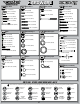
8 2.0 Race Roller Vehicle Setup 2 degrees of toe-out 27mm Differentials Front: x Standard Smart Spring Wire Dia: -1 degree Qty of Springs: Stock (20 degrees) Ramp Plate: 2.3mm Grease: 54/40 wt Losi Diff Fluid: 5000 wt Losi Silver 4.4 lbs 95mm Center: x Standard 95mm Long Down Smart Spring Wire Dia: Qty of Springs: Ramp Plate: 2/B Grease: 2/Inside Diff Fluid: 5000 wt Losi Losi LiPo 3 degrees 3 degrees 29mm -2 degrees Back 2.3mm 56/25 wt Losi Green 3.
A Division of Horizon Hobby, Inc. 4710 E. Guasti Road Ontario, CA 91761 Phone - 909-390-9595 Fax - 909-390-5356 WWW.LOSI.COM E-mail - feedback@losi.
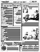
1 / 8 - S C A L E 4 W D C O M PE T I T I O N N I T R O B U G G Y R A C E R OL L ER OWNER’S MANUAL
INTRO q STEP I-01 Intro to the 8IGHT 2.0™ Manual Welcome Team Losi Racing 8IGHT 2.0 Owner! Thank you for selecting the 8IGHT 2.0 as your new racing buggy. The 8IGHT 2.0 has already distinguished itself as a top caliber racing chassis and as you will see, we have made every effort to produce a vehicle that is not only the most competitive but also easy to maintain.
Differentials Front: Standard Smart Spring Wire Dia: Qty of Springs: Ramp Plate: Grease: Diff Fluid: Center: Standard Smart Spring Wire Dia: Qty of Springs: Ramp Plate: Grease: Diff Fluid: 40
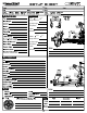
HARDWARE Cap Head Flat Head 1 2-56 x 1/4" (A6232) Flat Head 2 3 x 8mm (A9106) 2-56 x 1/2" (A6254) Button Head 2-56 x 1/4" (A6255) 8-32 x 3/8" (A6264) 4-40 x 1/4" (A6234) 3 x 12mm (A3500) 4-40 x 3/8" (A6206) 4-40 x 1/2" (A6204) 4-40 x 5/8" (A6221) 5-40 x 3/8" (A6277) 5-40 x 1/2" (A6271) 5-40 x 1/2" (A6240) 4-40 x 1/2" (A6256) 8-32 x 1/2" (A6262) 5-40 x 3/8" (A6270) 5-40 x 1/2" (A6278) 5-40 x 1-7/8" (A6273) 5-40 x 5/8" (A6275) 5-40 x 20mm (A6281) 5-40 x 3/4" (A6272) 5-40 x 7/8" w/ 5/8" S
INTRO TOOLS REQUIRED FOR ASSEMBLY Team Losi Racing has supplied all necessary Allen wrenches and special wrenches that are needed for assembly and adjustments. The following common tools will also be required: needle-nose pliers, regular pliers, hobby knife, scissors or other body cutting/trimming tools, and a soldering iron may be necessary for radio installation. 3/16", 1/4", 5/16" and 11/32" nut drivers are optional. RADIO/ELECTRONICS A suggested radio layout is provided in this manual.
STEP A q STEP A-01 q STEP A-02 Steering Link Assembly Servo Saver Assembly x1 x1 A9168 A9166 Steering Servo Steering Servo ArmArm 4-40 x 1/2" A6256 A4423 Servo Saver Tube L 4-40 x 3/16" A6306 Maintenance Tip A6043 A6045 Rod End Ball Rod Ball End A6043 A6045 Rod End Rod End LOSI-LOK x1 L 4-40 x 3/16" A6306 x1 5-40 x 5/8" A6045 A4423 Steering Arm A4412 Steering Drag Link x1 4-40 x 1/2" A6256 A4412 Drag Link Screw A4406 Steering Bell Crank R A4406 Steering Bell Crank L A4423 Servo Saver S
STEP A q STEP A-04 Steering/Top Plate Assembly x1 LOSI-LOK A4413 Front Chassis Brace 5-40 x 1/2" A6271 LOSI-LOK x2 5-40 x 1/2" A6278 A4424 Front Body Mount x1 5-40 x 3/8" A6270 x4 6x10x3mm A6946 q STEP A-05 Completed Steering Assembly 2
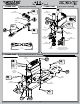
STEP B q STEP B-01 q STEP B-03 Ring Gear Assembly Complete Diff Assembly A3503 Outdrive Cup Solid x1 Fill with 5000 wt oil just above the planetary gear 2.5 x 12.80mm A3505 1 x4 3x12mm A3500 3 2 x1 F 8x14x4mm A6948 A3509 Ring Gear 4 A3505 O-ring A3502 Sun Gear x2 A3505 Diff Seal 6x11x0.2mm A3501 q STEP B-02 A3502 Planetary Gear Diff Case Assembly A3502 Planetary Gear Axle Solid x1 2.5 x 12.
STEP B q STEP B-04 Front Diff Install x1 F 8-32 x 1/8" A6298 To prevent fine dust from entering the gearbox, apply a thin bead of grease along the edge of the case as pictured. 3 LOSI-LOK 4 x2 A3514 Drive Adapter 5x11x4mm A6947 1 6 2 x2 5-40 x 7/8" A6273 x2 A4427 Front Diff Case A3508 Pinion Gear, Bevel 5 5-40 x 1/2" A6240 A4427 Front Diff Cover q STEP B-05 Front Spindle & CV Assembly A3535 CV Driveshaft Solid 1 A3523 CV Couple x1 2.5 x 12.
STEP B q STEP B-06 Spindle/Carrier Assembly x1 O 10-32 x 3/8" A6295 A1709 Left Spindle Carrier A6501 Hinge Pin x2 A1703 Left Front Arm 8/32 x 3/4" A6263 5 2 4 4 A1701 Front Arm Bushing x2 1 5 C 5-40 x 3/16" A6299 3 3 2 q STEP B-07 Front Suspension Arms Assembly A4431 Front Inner Hinge Pin Cap A1744 Front Inner Hinge Pin Brace Solid x2 4 x 65mm A6500 x4 5-40 x 3/4" A6272 A4431 Front Outer Hinge Pin Cap A1744 Front Outer Hinge Pin Brace 5
STEP B q STEP B-08 Sway Bar Assembly A1750 Sway Bar Link Install the Sway Bar Ball onto the Sway Bar Wire until the end of the wire is flush with the ball as pictured above. A1750 Sway Bar Ball A1750 Sway Bar Mount Cap x2 4-40 x 5/8" A6221 x2 A1750 Sway Bar, 2.3mm C 4-40 x 1/8" A6227 A1750 Sway Bar Ball x4 x2 C 5-40 x 1/8" A6228 2-56 x 1/4" A6232 q STEP B-09 Tie Rod/Shock Tower Assembly A6055 6.
STEP B q STEP B-10 Center CV Assembly Solid x1 2.5mm x 14mm A3253 A3526 CV Coupling, Center 1 2 LOSI-LOK x1 A3526 Driveshaft, Front Center q STEP B-11 F 5-40 x 1/8" A6228 Steering Rod Assembly Be sure to install the assembled Tie Rod onto the car with the groove (next to the center square section) on the driver’s left side for easier adjustment later.
STEP B q STEP B-12 Front Clip Assembly x2 5-40 x 3/4" A6279 x2 5-40 x 3/4" A6272 4 1 A4453 Front Bulkhead Spacer 3 2 x4 8-32 x 1/2" A6262 A4422 Front Bumper q STEP B-13 Completed Front Assembly 8
STEP C q STEP C-01 q STEP C-03 Ring Gear Assembly Solid Complete Diff Assembly x1 2.5 x 12.80mm A3505 Fill with 5000 wt oil just above the planetary gear. 3 x4 3x12mm A3500 A3502 Sun Gear 1 2 4 A3506 Center Outdrive x2 6x11x0.2mm A3501 x1 F 8x14x4mm A6948 A3505 O-ring A3516 48T Spur Gear A3505 Diff Seal A3502 Planetary Gear Axle q STEP C-02 Solid Diff Case Assembly A3502 Planetary Gear x1 2.5 x 12.80mm A3505 3 x2 AA3500 Diff Housing 6x11x0.
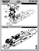
STEP C q STEP C-04 q STEP C-05 Center Top Brace Assembly (.5mm)(.020”) x1 x2 5mm E-clip A6109 F 5-40 x 1/8" A6297 Linkage Assembly A9168 Rear Brake Rod A9168 Front Brake Actuator LOSI-LOK A9168 Throttle Rod End x1 2-56 x 1/2" A6254 LOSI-LOK x2 x1 .250x.
STEP C q STEP C-08 Brake Caliper Assembly A3546 Front Brake Pad A3546 Rear Brake Pad .307" .307” 7.80mm 7.
STEP C q STEP C-10 Center Diff Installation Caution! Ensure that the driveshaft is inserted into the slot of the center outdrive while installing the Center Diff assembly.
STEP D q STEP D-01 q STEP D-03 Ring Gear Assembly Solid Complete Diff Assembly x1 2.5 x 12.80mm A3505 A3502 Sun Gear Fill with 2000 wt oil just above the planetary gear. 3 4 x2 6x11x0.2mm A3501 x4 2 3x12mm A3500 A3505 O-ring 1 A3510 Rear Ring Gear A3505 Diff Seal A3502 Planetary Axle x1 F 8x14x4mm A6948 A3503 Outdrive Cup q STEP D-02 A3502 Planetary Gear Diff Case Assembly Solid x1 A3502 Sun Gear 2.5 x 12.80mm A3505 3 4 A3500 Diff Housing Tighten the diff screws in this order.
STEP D q STEP D-04 Rear Diff Installation x1 A4414 Rear Chassis Support F 8-32 x 1/8" A6296 x1 A3514 Drive Adapter 5-40 x 7/8" A4414 LOSI-LOK 4 x2 A4451 Bearing Insert, LR 14x17x0.25mm A4452 3 x1 14x17x0.10mm A4452 5 x2 5x11x4mm A6947 1 x1 L 5-40 x 1/4" A6302 2 A4450 Rear Bulkhead x2 5-40 x 7/8" A6273 A3508 Pinion Gear The 8 2.0 comes with (2) .25mm shims and (1) .10mm shims on the left bearing insert. On the right bearing insert there are (3) .10mm shims.
STEP D q STEP D-06 Rear Suspension Arm Assembly A1749 3 toe/3 AntiSquat Pivot Brace x2 5-40 x 1-7/8" A6273 A4431 Rear Outer Pivot Brace Cap Solid x2 O 10-32 x 3/8" A6295 x2 5/40 x 3/4" A6272 x2 4 x 66mm A6500 A1725 Left Rear Arm A1745 Rear Pivot Brace A6503 3.5mm Hinge Pin A4431 Rear Inner Pivot Brace Cap x1 L 5-40 x 1/4" A6302 A4453 Hub Spacer .050” q STEP D-07 Sway Bar Assembly A1750 Sway Bar Link A1750 Rear Sway Bar, 2.
STEP D q STEP D-08 Wing Mount Assembly A4435 Wing Mount Brace A4435 Right Wing Mount x4 x2 5-40 x 3/4" A6279 L 5-40 x 1/4" A6302 A4435 Left Wing Mount x3 5-40 x 1/2" A6278 A4424 Rear Body Mount x2 L 8-32 x 11/32" A5438 Shock Stand-Off A1735 Rear Shock Tower q STEP D-09 Rear Shock Tower Installation x2 5-40 x 3/4" A6279 x2 5-40 x 1/2" A6278 16
STEP D q STEP D-10 Tie Rod Installation A6055 6.8mm Suspension Ball, Flanged x1 A6544 4mm Rear Turnbuckle 5-40 x 3/4" A6279 A6542 Rod End x2 5-40 x 1/4" A6302 x2 A6056 6.8mm Suspension Ball L 5-40 x 1/4" A6302 x1 5-40 x 1" A6280 3.79" 96.25 q STEP D-11 Center CV Assembly Solid x1 2.
STEP D q STEP D-12 Rear Clip Assembly x2 L 5-40 x 1/4" A6302 Caution! Ensure that the driveshaft is inserted into the slot of the center outdrive while installing the Rear Clip assembly.
STEP E q STEP E-01 • • • • • • • • • • • • • • Shock Assembly Clean the 2-56 x 1/4" Button Head Screw and apply Losi-Lok to the threads. Install the #54 Shock Piston on the front shock shaft and a #56 Shock Piston on the rear shock shaft using the 2-56 x 1/4" Button Screw into the Shock Shaft with a .050" Allen Wrench. Place a drop of Shock Oil into the bottom of the Shock Body to lubricate the Shock Seals. Thread the Shock Shaft into the Shock End using pliers.
STEP E q STEP E-02 x2 x2 Front Rear Shock Boot & Spring Assembly A5426 Shock Boot A5451 Silver Front Spring A5458 Green Rear Spring A5435 Spring Cup q STEP E-03 Front Shock Installation A5435 Shock Mount Bushing x2 L 5-40 x 1/4" A6302 x2 5-40 x 20mm A6281 x1 C 4-40 x 1/8" A6227 20
STEP E q STEP E-04 Rear Shock Installation A5435 Shock Mount Bushing x2 L 5-40 x 1/4" A6302 x1 C 4-40 x 1/8" A6227 q STEP E-05 Completed Shock Assembly 21 x2 5-40 x 20mm A6281
STEP F q STEP F-01 Chassis Guard Installation A4432 Chassis Guards x5 5-40 x 3/8" A6270 q STEP F-02 Switch Installation Supplied with switch (not included) x3 Optional Blank Switch Mount Plate If not using a switch, install the optional Blank Switch Mount Plate in place of the Switch Plate.
STEP F q STEP F-03 Servo Chart/Wiring Diagram Servo Spacer Servo Horn All (DZ9100T/S Needs Spacer) No 23T 94357Z, 94358Z, 94649Z, 94360Z, 94452Z, 94758Z, 94737Z, 94738Z Yes 94102Z, 94112Z Yes All No Servo Manufacturer, Make/Model JR Steering Servo Wires Sanwa Airtronics 23T Hitec Futaba All (S9102 DOES NOT FIT) 24T No 25T KO Propo No PDS-2123, 2344, 2363, 2365, 2366 Throttle Servo Wires Switch Wires 23T No Table2: Servo assembly and installation Airtronics® is a registered ma
STEP F q STEP F-05 Steering Servo Installation x4 A9168 Horn Insert 4-40 x 1/2" A6204 x4 #4 x .
STEP F q STEP F-07 Receiver Battery Door x2 Optional Battery Covers High Profile Cover should be used with Hump pack type receiver packs. Low Profile Cover should be used with LiPo type receiver packs.
STEP F q STEP F-09 Servo Horn Installation Supplied with servo (Not Included) Ensure the servo gear is centered before attaching the Servo Horns. This is best accomplished by connecting the servos to the radio system and setting the trim to center.
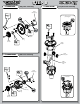
STEP G q STEP G-01 Clutch Assembly A9107 Composite Clutch Shoe A9113 Clutch Spring Green Composite Shoe LOSI-LOK A9105 Aluminum Flywheel A9105 Flywheel Collet 1 Aluminum Shoe 2 A9106 Clutch Pins q STEP G-02 A9103 Clutch Nut Clutch Bell Assembly Use the appropriate number of shims to achieve proper clutchbell end play. Generally .25mm to .50mm is x2 optimum. 5x7x0.2mm A9106 x1 5x13x4mm A6949 x1 A9106 Clutch Spacer 5x7x0.
STEP G q STEP G-03 Engine Mount Assembly x4 LOSI-LOK 5-40 x 1/2" A6240 x4 Ball Stud A6215 Pipe/Header (Not supplied) A9154 Right Engine Mount q STEP G-04 A9154 Left Engine Mount Air Filter Assembly Tech Tip With a clean rag or paper towel take the air filter and squeeze it between the rag to remove any excess air filter oil. The goal is to remove all the oil blotches from the filter to improve engine performance.
STEP G q STEP G-05 Air Filter Installation 1 2 q STEP G-06 Pipe Mount Assembly x1 8-32 x 1/8" A6298 Trim pipe mount in small increments as needed to mount pipe. Ensure that the wire clears all steering components.
STEP G q STEP G-07 • • • • Engine Installation Adjust the gear mesh between the Clutch Bell and the Spur gear by sliding the engine mounts in the slots of the chassis. In order to function properly, the Gears should be as close as possilbe, but still have a small amount of backlash (space between the Gear teeth). Place a piece of paper between the Clutch Bell gear and Spur gear, slide the engine sideways until the paper is pinched between the gears and tighten the engine mount screws.
STEP H q STEP H-01 Tire Mounting 1 2 A7763B XBT™, Blue 1/8 Buggy Foam Insert. Only sold with Tires. A7751 1/8 Buggy Wheel, Yellow q STEP H-02 • • Tire Gluing The tires are already glued to the wheels. Here are the steps to show you how to complete this process. This can be done by using a fast-curing super glue or cyanoacrylate glue (LOSA7880, LOSA7881), available at your local hobby shop.
STEP H q STEP H-03 Tire Installation LOSI-LOK A3531 Wheel Hexes LOSI-LOK q STEP H-04 Wing Installation 1 A8130 Wing Button x2 Body Clip A8200 2 A8130 Rear Wing 32
STEP H q STEP H-05 Body Painting & Trimming Painting: Prepare the Lexan Body for painting by washing it thoroughly (inside and out) with warm water and liquid detergent. Dry the body with a clean, soft cloth. Use the supplied window masks to cover the windows from the inside. A high-quality masking tape should be used on the inside of the body to mask off any stripes, panels, or designs that you wish to paint on the body. Use acrylic lacquer or other paints recommended for Lexan (polycarbonate).
STEP H q STEP H-06 Body Mounting A8095 Body Spacer x2 Body Clip A8200 34
STEP H q STEP H-07 Completed Chassis Assembly 35
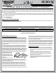
CHECKLIST BEFORE RUNNING YOUR NEW 8IGHT 2.0 OFF-ROAD RACING BUGGY for the first time, you should run down the following checklist in order and complete the listed tasks. We’re sure you’re anxious to get out and run your new 8IGHT 2.0 now that it’s built, but please note that fine-tuning of the initial setup is an essential part of building a high-performance racing buggy such as your new 8IGHT 2.0.
SETUP GUIDE TIPS AND HINTS FROM THE TEAM Before you start making changes on your 8IGHT 2.0 Off-Road Racing buggy, you need to make a few decisions. First of all, tires, and how they are set up, have a tremendous impact on overall performance. Before you start making changes on the chassis setup, take a moment to observe a few of the fastest cars at the track and what type of tire and inner liner they are running.
SETUP GUIDE Rear Toe-in: The 8IGHT 2.0 is equipped with 3 degrees of toe-in per side. Less rear toe-in will increase the wheel base of the buggy and decrease forward traction, but will increase top speed and side traction in the middle of a turn. More toe-in will increase forward traction, have more off-power steering and less side traction. Wheel Base: The 8IGHT 2.0 is equipped with a long wheelbase.
SETUP GUIDE Shock Mounting Positions: More inclined (moving the shocks in on the tower) has softer initial damping and is more forgiving. Less inclined (moving the shocks out on the tower) makes the car more responsive and is better for technical tracks. Ackerman: A long Ackerman plate will have smooth off-power steering and is more forgiving. The long Ackerman plate will have more steering on-power. A short Ackerman plate responds quicker and has more steering in the middle of the turn.