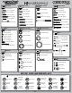
8IGHT-E 2.0 Race Roller Vehicle Setup 2 degrees of toe out 27mm Differentials Front: x Standard Smart Spring Wire Dia: -1 degree Qty of Springs: Stock(20 degrees) Ramp Plate: 2.3mm Grease: 54/40wt Losi Diff Fluid: Losi 5000wt Silver 4.4lbs See shock length 95mm Long Center: x Standard Spring Wire Dia: Qty of Springs: Down Ramp Plate: 2/B Grease: 2/Inside Smart Diff Fluid: Losi 5000wt 3 degrees 3 degrees 29mm -2 degrees Back 2.3mm 56/25wt Losi Green 3.
Back Cover UNITED STATES: 4710 E. Guasti Road Ontario, CA 91761 Phone: 909-390-9595 Fax: 909-390-5356 UNITED KINGDOM: Units 1-4 Ployters Rd Staple Tye Harlow, Essex CM18 7NS Phone: +44 (0) 1279 641 097 WWW.LOSI.COM E-mail - feedback@losi.
Front Cover ® 1/8-SCALE 4WD COMPETITION ELECTRIC BUGGY RACE ROLLER OWNER’S MANUAL
INTRO q STEP I-01 Intro to the 8IGHT-E 2.0™ Manual Welcome Team Losi Racing 8IGHT-E 2.0 Owner! Thank you for selecting the 8IGHT-E 2.0 as your new racing buggy. The 8IGHT-E 2.0 has already distinguished itself as a top caliber racing chassis and as you will see, we have made every effort to produce a vehicle that is not only the most competitive but also easy to maintain.
Differentials Front: Standard Smart Spring Wire Dia: Qty of Springs: Ramp Plate: Grease: Diff Fluid: Center: Standard Smart Spring Wire Dia: Qty of Springs: Ramp Plate: Grease: Diff Fluid: Notes: 32
HARDWARE Cap Head Flat Head 1 2-56 x 1/4" (A6232) Flat Head 2 3 x 8mm (A9106) 2-56 x 1/2" (A6254) Button Head 2-56 x 1/4" (A6255) 8-32 x 3/8" (A6264) 4-40 x 1/4" (A6234) 3 x 12mm (A3500) 4-40 x 3/8" (A6206) 4-40 x 1/2" (A6204) 4-40 x 5/8" (A6221) 5-40 x 3/8" (A6277) 4mm x 12mm (A6259) 5-40 x 1/2" (A6271) 5-40 x 1/2" (A6240) 4-40 x 1/2" (A6256) 8-32 x 1/2" (A6262) 5-40 x 3/8" (A6270) 5-40 x 1/2" (A6278) 5-40 x 5/8" (A6275) 5-40 x 20mm (A6281) 5-40 x 1-7/8" (A6273) 5-40 x 3/4" (A6272) 5-4
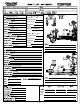
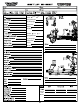
INTRO TOOLS REQUIRED FOR ASSEMBLY Team Losi Racing has supplied all necessary Allen wrenches and special wrenches that are needed for assembly and adjustments. The following common tools will also be required: needle-nose pliers, regular pliers, hobby knife, scissors or other body cutting/trimming tools, and a soldering iron may be necessary for radio installation. 3/16", 1/4", 5/16" and 11/32" nut drivers are optional. RADIO/ELECTRONICS A suggested radio layout is provided in this manual.
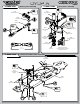
STEP A q STEP A-01 q STEP A-02 Steering Link Assembly Servo Saver Assembly x1 x1 A9168 A9166 Steering Servo Steering Servo ArmArm 4-40 x 1/2" A6256 A4423 Servo Saver Tube L 4-40 x 3/16" A6306 Maintenance Tip A6043 A6045 Rod End Ball Rod Ball End A6043 A6045 Rod End Rod End LOSI-LOK x1 L 4-40 x 3/16" A6306 x1 5-40 x 7/8" A6045 A4423 Steering Arm A4412 Steering Drag Link x1 4-40 x 1/2" A6256 A4412 Drag Link Screw A4406 Steering Bell Crank R A4406 Steering Bell Crank L A4423 Servo Saver S
STEP A q STEP A-04 Steering/Top Plate Assembly A4424 Front Body Mount x1 5-40 x 1/2" A6271 LOSI-LOK A4413 Front Chassis Brace x2 5-40 x 1/2" A6278 x1 5-40 x 3/8" A6270 LOSI-LOK x4 6x10x3mm A6946 q STEP A-05 Completed Steering Assembly 2
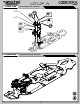
STEP B q STEP B-01 q STEP B-03 Ring Gear Assembly Complete Diff Assembly A3503 Outdrive Cup Solid x1 Fill with 5000 wt oil just above the planetary gear 2.5 x 12.80mm A3518 1 x4 3x12mm A3500 3 2 x1 F 8x14x4mm A6948 A3509 Ring Gear 4 A3505 O-ring A3502 Sun Gear x2 A3505 Diff Seal 6x11x0.2mm A3501 q STEP B-02 A3502 Planetary Gear Diff Case Assembly A3502 Planetary Gear Axle Solid x1 2.5 x 12.
STEP B q STEP B-04 Front Diff Install x1 F 8-32 x 1/8" A6296 To prevent fine dust from entering the gearbox, apply a thin bead of grease along the edge of the case as pictured. 3 LOSI-LOK 4 x2 A3514 Drive Adapter 5x11x4mm A6947 1 6 2 x2 5-40 x 7/8" A6273 A4427 Front Diff Case A3508 Pinion Gear, Bevel 5 x2 5-40 x 1/2" A6240 A4427 Front Diff Cover q STEP B-05 Front Spindle & CV Assembly A3535 CV Driveshaft Solid 1 A3523 CV Couple x1 2.5 x 12.
STEP B q STEP B-06 Spindle/Carrier Assembly x1 O 10-32 x 3/8" A6295 A1709 Left Spindle Carrier A6501 Hinge Pin x2 A1703 Left Front Arm 8/32 x 3/4" A6263 5 2 4 4 A1701 Front Arm Bushing x2 1 5 C 5-40 x 3/16" A6299 3 3 2 q STEP B-07 Front Suspension Arms Assembly A4431 Front Inner Hinge Pin Cap A1744 Front Inner Hinge Pin Brace Solid x2 4 x 65mm A6500 x4 5-40 x 3/4" A6272 A4431 Front Outer Hinge Pin Cap A1744 Front Outer Hinge Pin Brace 5
STEP B q STEP B-08 Sway Bar Assembly A1750 Sway Bar Link Install the Sway Bar Ball onto the Sway Bar Wire until the end of the wire is flush with the ball as pictured above. A1750 Sway Bar Ball A1750 Sway Bar Mount Cap x2 4-40 x 5/8" A6221 x2 A1750 Sway Bar, 2.3mm C 4-40 x 1/8" A6227 A1750 Sway Bar Ball x4 x2 C 5-40 x 1/8" A6228 2-56 x 1/4" A6232 q STEP B-09 Tie Rod/Shock Tower Assembly A6055 6.
STEP B q STEP B-10 Center CV Assembly Solid x1 2.5mm x 14mm A3518 A3526 CV Coupling, Center 1 2 LOSI-LOK x1 A3526 Driveshaft, Front Center q STEP B-11 F 5-40 x 1/8" A6228 Steering Rod Assembly Be sure to install the assembled Tie Rod onto the car with the groove (next to the center square section) on the driver’s left side for easier adjustment later.
STEP B q STEP B-12 Front Clip Assembly x2 5-40 x 3/4" A6279 x2 5-40 x 3/4" A6272 4 1 A4453 Front Bulkhead Spacer 3 2 x4 8-32 x 1/2" A6262 A4422 Front Bumper q STEP B-13 Completed Front Assembly 8
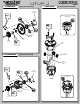
STEP C q STEP C-01 q STEP C-03 Ring Gear Assembly Solid Complete Diff Assembly x1 2.5 x 12.80mm A3518 Fill with 5000 wt oil just above the planetary gear. 3 x4 3x12mm A3500 A3502 Sun Gear 1 2 4 A3506 Center Outdrive x2 x1 6x11x0.2mm A3501 F 8x14x4mm A6948 A3505 O-ring A3505 Diff Seal A3562 45T Plastic Spur Gear A3502 Planetary Gear Axle q STEP C-02 Solid Diff Case Assembly A3502 Planetary Gear x1 2.5 x 12.
STEP C q STEP C-04 Center Motor Mount Assembly x4 5-40 x 1/2" A6271 LOSI-LOK A4462 Diff Top Plate A9198 Motor Mount A4420 Center Diff Mount q STEP C-05 Motor Installation B9385 Pre-Assembled Motor Leads, 1/8th Xcelorin x1 8-32 x 1/2" A6264 B9422 2100Kv Xcelorin Motor LOSI-LOK x1 #4 Countersink A6351 LOSI-LOK A9199 Motor Adapter x1 x2 4mm x 12mm A6259 Setscrew A3575 10 A3575 1.
STEP C q STEP C-06 Center Differential Installation A4462 Center Diff Standoff Plate x4 #8 Countersink A6351 x2 8-32 x 3/8" A6264 x4 8-32 x 1/2" A6262 q STEP C-07 Completed Center Diff Assembly 11
STEP D q STEP D-01 q STEP D-03 Ring Gear Assembly Solid Complete Diff Assembly x1 2.5 x 12.80mm A3518 A3502 Sun Gear Fill with 2000 wt oil just above the planetary gear. 3 4 2 x4 3x12mm A3500 x2 6x11x0.2mm A3501 A3505 O-ring 1 A3510 Rear Ring Gear A3505 Diff Seal A3502 Planetary Axle x1 F 8x14x4mm A6948 A3503 Outdrive Cup q STEP D-02 A3502 Planetary Gear Diff Case Assembly Solid x1 A3502 Sun Gear 2.5 x 12.80mm A3518 3 4 A3500 Diff Housing Tighten the diff screws in this order.
STEP D q STEP D-04 Rear Diff Installation x1 A4414 Rear Chassis Support F 8-32 x 1/8" A6296 x1 A3514 Drive Adapter 5-40 x 7/8" A4414 LOSI-LOK 4 x2 A4451 Bearing Insert, LR 14x17x0.25mm A4452 3 x1 14x17x0.10mm A4452 5 x2 5x11x4mm A6947 1 x1 L 5-40 x 1/4" A6302 2 A4450 Rear Bulkhead x2 5-40 x 7/8" A6273 A3508 Pinion Gear The 8IGHT-E 2.0 comes with (2) .25mm shims and (1) .10mm shims on the left bearing insert. On the right bearing insert there are (3) .10mm shims.
STEP D q STEP D-06 Rear Suspension Arm Assembly A1749 3 toe/3 Anti-Squat Pivot Brace x2 5-40 x 1-7/8" A6273 A4431 Rear Outer Pivot Brace Cap Solid x2 O 10-32 x 3/8" A6295 x2 5/40 x 3/4" A6272 x2 4 x 66mm A6500 A1725 Left Rear Arm A1745 Rear Pivot Brace A6503 3.5mm Hinge Pin A4431 Rear Inner Pivot Brace Cap x1 L 5-40 x 1/4" A6302 A4453 Hub Spacer .050” q STEP D-07 Sway Bar Assembly A1750 Sway Bar Link A1750 Rear Sway Bar, 2.
STEP D q STEP D-08 Wing Mount Assembly A4435 Wing Mount Brace A4435 Right Wing Mount x4 x2 5-40 x 3/4" A6279 L 5-40 x 1/4" A6302 A4435 Left Wing Mount x3 5-40 x 1/2" A6278 A4424 Rear Body Mount x2 L 8-32 x 11/32" A6311 A5438 Shock Stand-Off A1735 Rear Shock Tower q STEP D-09 Rear Shock Tower Installation x2 5-40 x 3/4" A6279 x2 5-40 x 1/2" A6278 15
STEP D q STEP D-10 Tie Rod Installation A6055 6.8mm Suspension Ball, Flanged x1 A6544 4mm Rear Turnbuckle 5-40 x 3/4" A6279 A6542 Rod End x2 5-40 x 1/4" A6302 x2 A6056 6.8mm Suspension Ball L 5-40 x 1/4" A6302 x1 5-40 x 1" A6280 3.79" 96.25 q STEP D-11 Center CV Assembly Solid x1 2.
STEP D q STEP D-12 Rear Clip Assembly x2 L 5-40 x 1/4" A6302 Caution! Ensure that the driveshaft is inserted into the slot of the center outdrive while installing the Rear Clip assembly.
STEP E q STEP E-01 • • • • • • • • • • • • • • Shock Assembly Clean the 2-56 x 1/4" Button Head Screw and apply Losi-Lok to the threads. Install the #54 Shock Piston on the front shock shaft and a #56 Shock Piston on the rear shock shaft using the 2-56 x 1/4" Button Screw into the Shock Shaft with a .050" Allen Wrench. Place a drop of Shock Oil into the bottom of the Shock Body to lubricate the Shock Seals. Thread the Shock Shaft into the Shock End using pliers.
STEP E q STEP E-02 x2 x2 Front Rear Shock Boot & Spring Assembly A5426 Shock Boot A5451 Silver Front Spring A5458 Green Rear Spring A5435 Spring Cup q STEP E-03 Front Shock Installation A5435 Shock Mount Bushing x2 L 5-40 x 1/4" A6302 Tip: Ensure the open end of the shock cup is facing the outside on the vehicle x2 5-40 x 20mm A6281 x1 C 4-40 x 1/8" A6227 19
STEP E q STEP E-04 Rear Shock Installation x2 L 5-40 x 1/4" A6302 Tip: Ensure the open end of the shock cup is facing the outside on the vehicle A5435 Shock Mount Bushing x2 5-40 x 20mm A6281 x1 C 4-40 x 1/8" A6227 q STEP E-05 Completed Shock Assembly 20
STEP F q STEP F-01 Chassis Guard Installation A4432 Chassis Guards x5 5-40 x 3/8" A6270 q STEP F-02 Steering Servo Installation A9167 Servo Horn Adapter Servo Manufacturer, Make/Model Servo Spacer Servo Horn No 94357Z, 94358Z, 94649Z, 94360Z, 94452Z, 94758Z, 94737Z, 94738Z Yes 94102Z, 94112Z Yes Hitec All No 24T Futaba All (S9102 DOES NOT FIT) No 25T JR All (DZ9100T/S Needs Spacer) Sanwa Airtronics KO Propo PDS-2123, 2344, 2363, 2365, 2366 x4 4-40 x 1/2" A6204 23T x4 #4x.
STEP F q STEP F-03 Receiver/Antenna Tube Assembly A4403 Antenna Cap A8313 Name Plate A4402 Antenna Tube A4460 Receiver Cover x1 Body Clip A8200 q STEP F-04 Radio Tray Installation x2 8-32 x 3/8" A6264 22
STEP F q STEP F-05 Servo Horn Installation Tip: If you are using a metal output splined servo be sure to use Losi Lok on the screw. Supplied with Servo (not included) Ensure the servo gear is centered before attaching the Servo Horns. This is best accomplished by connecting the servo to the radio system and setting the trim to center.
STEP F q STEP F-07 Battery Tray Installation x2 #8 Countersink A6351 x3 8-32 x 3/8" A6264 x1 5-40 x 1/2" A6271 Speed Controller Lead Wire (Connect to Channel 2 in Receiver) q STEP F-08 Completed Radio Tray and Battery Installation 24
STEP G q STEP G-01 Tire Installation LOSI-LOK A3531 Wheel Hexes LOSI-LOK A3531 Wheel Hexes q STEP G-02 Wing Installation 1 A8130 Wing Button A8130 Rear Wing 2 x2 Body Clip A8200 25
STEP G q STEP G-03 Completed Chassis Assembly q STEP G-04 Painting the Body Painting: Prepare the Lexan Body for painting by washing it thoroughly (inside and out) with warm water and liquid detergent. Dry the body with a clean, soft cloth. Use the supplied window masks to cover the windows from the inside. A high-quality masking tape should be used on the inside of the body to mask off any stripes, panels, or designs that you wish to paint on the body.
CHECKLIST BEFORE RUNNING YOUR NEW 8IGHT-E 2.0 OFF-ROAD RACING BUGGY for the first time, you should run down the following checklist in order and complete the listed tasks. We’re sure you’re anxious to get out and run your new 8IGHT-E 2.0 now that it’s built, but please note that fine-tuning of the initial setup is an essential part of building a high-performance racing buggy such as your new 8IGHT-E 2.0.
SETUP GUIDE TIPS AND HINTS FROM THE TEAM Before you start making changes on your 8IGHT-E 2.0 Off-Road Racing buggy, you need to make a few decisions. First of all, tires, and how they are set up, have a tremendous impact on overall performance. Before you start making changes on the chassis setup, take a moment to observe a few of the fastest cars at the track and what type of tire and inner liner they are running.
SETUP GUIDE Differentials: The 8IGHT-E 2.0 comes equipped with 5000 wt in the front and center diff, and 2000 wt in the rear diff. Thinner front differential oil increases offpower steering, but if the oil is too thin the steering will become grabby and inconsistent. Thicker front differential oil increases off-power stability and increases on-power steering. Thinner center differential has less forward drive, can unload more under acceleration and is easier to drive on rough and slick tracks.
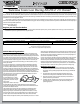
Warranty Warranty Period Horizon Hobby, Inc., (Horizon) warranties that the Products purchased (the “Product”) will be free from defects in materials and workmanship at the date of purchase by the Purchaser. Limited Warranty (a) This warranty is limited to the original Purchaser (“Purchaser”) and is not transferable. REPAIR OR REPLACEMENT AS PROVIDED UNDER THIS WARRANTY IS THE EXCLUSIVE REMEDY OF THE PURCHASER. This warranty covers only those Products purchased from an authorized Horizon dealer.
Warranty United States: Electronics and engines requiring inspection or repair should be shipped to the following address: Horizon Service Center 4105 Fieldstone Road Champaign, Illinois 61822 All other Products requiring warranty inspection or repair should be shipped to the following address: Horizon Product Support 4105 Fieldstone Road Champaign, Illinois 61822 Please call 877-504-0233 or e-mail us at productsupport@horizonhobby.com with any questions or concerns regarding this product or warranty.