
User Manual


25
2525
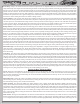
2-56 x 3/16” (A6239)
4-40 x 3/8” (A6210)
4-40 x 1/2” (A6220)
4-40 x 1/8” (A6227)
4-40 x 7/16” (A6248)
Locating Pin (A6243)
5-40 x 3/16” (A9757)
4-40 x 3/8” (A6206)
4-40 x 1/2” (A6204)
4-40 x 3/4” (A6205)
2-56 x 5/16” (A5330)
#4 x .030 (Gold) (A6350)
Belleville (A2909)
4mm x 5mm x 0.5mm (A6108)
3/16” x 5/16” x .015” (A6230)
3/16” x 5/16” x .130” (A6365)
1/8” x 1/16” (.0625”) (A2127)
1/8” x .120” (“A”) (A5321)
1/8” x .140” (“B”) (A5321)
5mm x 8mm (A6907)
3/16” x 3/8” (A6916)
4mm x 8mm (A6936)
1/2” x 3/4”
(A6910)
4mm C-Clip (A6108)
3/32” E-Clip (A6103)
4mm E-Clip (A6106)
2-56 x 1/4” (A6232)
4-40 x 5/16” (A6245)
4-40 x 3/8” (A6229)
3mm x 6mm (A6238)
4-40 x 5/16” ALUM. (NA)
4-40 x 1/4” (A6234)
Female (A6009)
1/8” Standard Neck (A6004)
.200 Short Neck (A6008)
.345 Short Neck (A6007)
3/16” Standard Neck (A6001)
1/16” x 5/16” Roll (A6401)
1/16” x 5/16” Solid LCD (A3335)
.067” x 7/16” Solid (A6401)
3/32” x .930” Hinge (A6081)
1/8” x 2.125” Hinge (A6094)
.065” x 7/16” Solid CVD (A9933)
.067” x 5/16” Solid (A6406)
L 4-40 x 3/16” (Mini) (A6306)
L 4-40 x 1/4”
(A6308)
L 8-32 x 11/32”
(A6310)
FL 4-40 x 1/4” (Nylon) (A6301)
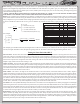
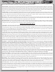
DETAIL ICON REFERENCE KEY
HARDWARE
Cap Head Flat Head Button Head Set
Ball Studs Washers Metal Shims Plastic Spacers
Ball Bearings Roll/Solid Pins E/C-Clips Nuts (Lock/Plain)
LOCTITE
Apply Loctite®
GREASE
CLEAR
Apply Clear
Grease
GLUE
Apply CA Glue
GREASE
Apply Synthetic
White Grease
OIL
Fill With
Silicone Oil
Apply Heat
Pay Special
Attention
CUT
Cut/Trim
Ensure Free
Movement
Ensure Free
Rotation
Ensure Proper
Orientation
Push Firm
Tighten
L
R
L
R
Assemble Other
Side the Same
L
Side Shown
x2
Repeat/Build
Multiple
Screw Partially
DO NOT
Over Tighten/
Snug Tight
1
These numbers are used to identify the critical order in which assembly must occur. *Note: They will not call out every part of the step.