
User Manual


22
2222
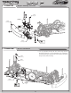
Front Droop: Droop is the amount of down-travel that the suspension has. It is adjusted with the set screw from the top of the arm. Droop is
easily measured by removing the front tires and setting the chassis on the droop gauge (included) so that the gauge extends across the chassis
from the center, out to the arm with the graduated notches to one side. Slide the gauge inward using the set screw boss on the bottom of the
spindle carrier as a reference. The set screw boss should just clear the 3mm (minimum) step on the droop gauge. Repeat this for the other side,
making sure that both sides are the same. With standard 2.5” tall tires you will want to maintain between 3-5mm of droop. Less droop makes
the chassis react quicker but is not as good on bumpy tracks. More droop reduces steering into a turn and slows down the overall reaction of
the chassis as well as making the chassis more stable on bumpy surfaces.
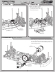
Up-travel Limiters: The up-travel of the shocks can be adjusted via the setscrew in the sway bar mount/up-travel stop (attached to each of the
arms). With the chassis pushed down onto a fl at surface (suspension compressed), pull up on the front or rear tires. This is the up-travel of the
car. More up-travel is recommended for bumpy surfaces or track layouts that use berm edging or track dots. This will allow the suspension
to work over those objects. Testing has shown that 3-5mm of tire up-travel for this type of track conditions is best. For smooth track layouts
that are high bite, testing showed that limiting the up-travel helps the car react faster and improves corner speed.
Kickup/Anti-dive: This is the angle of the inner front hinge pins in relation to the chassis. The amount of kickup/anti-dive is controlled with
shims (one .035” shim per degree) under the pivot blocks that mount the inner hinge pins and suspension arms to the chassis. For kickup, the
shims will be placed under the pivot block in front of the arms. For anti-dive, the shims will be placed under the pivot blocks directly behind
the front arms. Front kick-up generally makes the car easier to drive, especially on bumpy tracks, and will give more steering entering a turn.
However, you will loose on-power (exit) steering. Anti-dive will make the steering feel more aggressive initially, and deliver more on-power
steering. Anti-dive will also improve ‘braking traction’ but will reduce the chassis’ ability to handle bumpy surfaces.
Caster: This is the angle of the kingpin from vertical when viewed from the side of the car. The JRX-S comes equipped with 4-degree
spindle carriers, however, this can be adjusted from 0-8 degrees with aftermarket carriers. Total caster is determined by adding the amount of
kickup/anti-dive and the kingpin angle of the front spindle carriers. On asphalt, increasing total caster will provide more steering entering a
turn but less on exit. Decreasing total caster will cause the steering to react faster and increase on-power steering. For carpet/foam tire racing,
decreasing total caster will cause the car to react faster off-center and decrease on-power steering. Increasing total caster will cause the car to
be smoother off-center and provide more total steering. Testing has shown that the 6 degree carriers perform best for this type of racing.
Inboard Pin Angle: The inboard angle of the front hinge pins is adjustable in 1 degree increments from 0 to +2 degrees (angled out). The car
comes stock with a 1 degree front pivot. The kit also includes the 0 and +2 degree blocks for adjustment. Running less inboard front toe (0
degree) will result in more stability by decreasing steering into a turn. Increasing inboard front toe (+2 degrees) will provide more aggressive
feel to the steering.
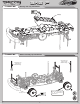
Front Drive: The JRX-S comes with a front differential, however, the front drive can be changed to an optional one-way or spool (using
special spool pads in place of the diff balls to create a locked differential). A front diff will give you the most consistent feel and provide more
off-power steering while sacrifi cing a little forward drive. One-way’s are used on high traction asphalt and carpet tracks that are fl owing with
no hairpin turns. A one-way lets the front tires “free wheel” individually for greater steering when you let off the throttle, and becomes a solid
axle when power is applied. By creating a solid front axle, the one-way increases acceleration compared to a diff. A one-way has no front
braking ability so all braking is done at the rear, which can be diffi cult. A spool is a locked front axle and has the best of both one-way and
diff characteristics. The use of a spool allows precise off-power braking while maintaining the benefi ts of solid axle acceleration on-power.
The front of the JRX-S is equipped with the new Team Losi LCD (Losi Constant Drive, Patent Pending) axles. The front drive axles were
designed exclusively for spool type racing to eliminate the chatter that spools cause at high steering angles. Be sure to use these for all types
of racing since they will greatly enhance steering and overall handling of your JRX-S.
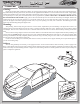
Tuning the Rear End of the JRX-S
Toe-In: Having the same defi nition as for the front end, the toe-in can be adjusted on the JRX-S with either the rear outer pivot or the rear
hubs. The stock toe-in is 2 degrees of inboard and 0 degrees in the hub. Increasing rear toe-in will increase forward traction and initial steer-
ing, but reduce straightaway speed. Decreasing rear toe-in will decrease forward traction and “free-up” the car. Less toe-in can be used for
stock racing to gain top speed.
Inboard Pin Angle: Placing all of the toe-in inboard will cause the weight to transfer to the front end easily, increasing off-power steering
and decreasing on-power steering (more forward traction). Placing all of the toe-in in the hubs will stabilize the weight transfer, providing
less initial steering entering a turn, and less forward traction.
Camber Location: The
JRX-S has multiple rear camber locations. Using a longer camber link will improve stability and traction (grip).
Using a shorter camber link will increase steering while decreasing rear grip. Running the camber link in the inside position (A) on the hub
will generate more rotation entering a turn, but decrease steering on exit. Running the camber link in the outer position (B) on the hub will
generate more stability entering a turn and increase steering on exit. Testing has shown that running the inboard rear camber ball stud in a
higher location (less angle relative to arm = less camber gain) on high traction surfaces offers improved stability with decreased rear grip.
Also, on low traction surfaces, running the inboard rear camber ball stud in a lower location (more angle relative to arm = more camber gain)
will increase rear grip.
Static Camber: Having the same defi nition as for the front end and measured in the same fashion, rear camber can also be a critical tuning
feature. Testing has shown that running a small amount of negative camber (.5-1 degree) is best. Increasing negative rear camber (in the range
of 1.5-3 degrees) will increase stability and traction in corners, but decrease high speed stability. Decreasing rear camber (in the range of 0-1.5
SETUP GUIDE