/10 Scale 2wd Nitro Powered Off-Road Racing Truck XXX-NT AD2 O WNER'S MANU AL OWNER'S MANUAL Carefully read through all instructions to familiarize yourself with the parts, construction technique, and tuning tips outlined in this manual. Being able to grasp the overall design of your new XXX-NT AD2 racing truck before begining the construction process will ensure a smooth assembly. Take your time and pay close attention to detail. Keep this manual for future reference.
WEL COME XXX-NT AD2 O WNER! WELCOME OWNER! Thank you for choosing the Team Losi XXX-NT ADAM DRAKE, Edition 2. During the past year, I, along with Team Losi engineers and team members, have done extensive testing and development to give you the truck you just purchased. In addition to the many specialty parts used on my previous race winning truck.
RADIO/ELECTRICAL A suggested radio layout is provided in this manual. Your high performance R/C center should be consulted regarding specifics on radio/ electrical equipment. However, we recommend using a steering servo with a minimum of 50 oz-in of torque. HARDWARE IDENTIFICATION When in question, use the hardware identification guide in each step. For screws, the prefix number designates the screw size and number of threads per inch (i.e., 4-40 is #4 screw with 40 threads per inch of length).
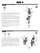
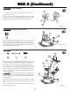
BAG A Step A-1 Servo Saver Assembly: 6 5 6 4 3 1. Place the Servo Saver Bottom (1) over the Servo Saver Post (2) and slide the Servo Saver Bottom all the way against the hex at the opposite end. Be sure that the hex on the Servo Saver Post is inserted into the hex in the Servo Saver Bottom. 2. Slide the Servo Saver Top (3) down over the Servo Saver Post so that the 'V' area of the Servo Saver Top rests in the 'V' area of the Servo Saver Bottom.
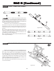
BAG A (Contin ued) (Continued) Step A-3 Servo Draglink: 8 1 *NOTE: Be sure to snap each end of the Draglink onto the correct Ball Stud as shown! 1. Snap one end of the steering Draglink (12) onto the rear Ball Stud (11) on the Servo Saver Bottom (1). Snap the other end of the Draglink onto the rear Ball Stud on the steering Idler Arm (8). 11 11 12 Figure A-3 Step A-4 Threaded Insert Install: 14 18 18 1.
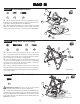
BAG B Step B-1 Front Bulkhead Install: 38 9 9 38 20 1. Secure the front Kickplate (14) to the front Bulkhead (32) by 32 threading a 4-40 x 3/8" Flat Head Screw (20) through the center hole in the front of the Kickplate and into the Bulkhead. 2. Place one Ball Stud Washer (9) over each of the two 3/8" Ball Studs (38). Thread the 3/8" Ball Stud into the outside of the three camber position holes (#3 hole), on each side of the front Bulkhead.
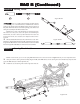
BAG B (Contin ued) (Continued) Step B-4 Spindle Carrier Assembly: 45 47 46 119 44 1. Insert a front Axle (39) into each of the front Spindles [left 45 (42), right (40)] as shown. The hole in the Axle should line up with the hole in the Spindle. 2. Attach the left Spindle (42) to the left Spindle Carrier (43) by aligning the holes in each part and inserting a 1/8" x 1.250" Hinge Pin (44) from the bottom. Do not insert the Pin all the way through both parts yet. 3. Insert a plastic .
BAG B (Contin ued) (Continued) Step B-6 Front Suspension Assembly: 51 50 46 1. Place the left Spindle and Carrier assembly (Figure B-6) into a front suspension Arm (48) as shown in Figure B-6. Note that the Spindle Arm faces the side of the suspension Arm with the Shock mount holes (rear) and the Ball Stud (72) in the Spindle Carrier is pointing forward. Line up the two sets of holes in the left Spindle Carrier (43) with the holes in the front Arm.
BAG B (Contin ued) (Continued) Step B-8 Tierod - Camber Link Assembly: 71 54 55 55 There is a small container/package of White Grease (71) in this bag. It is recommended that a small amount of this be applied to the threads of the Turnbuckles before trying to thread on the plastic Rod Ends. Please use this lube sparingly as it will be used during the assembly of the Differential as well. *NOTE: The two ends of the Turnbuckle are threaded opposite.
BAG B (Contin ued) (Continued) Step B-10 Steering Tierod: 54 55 Figure B-10A 54 There is a small container/package of White Grease (71) in this bag. It is recommened that a small amount of this be applied to the threads of the Turnbuckles before trying to thread on the plastic Rod Ends. Please use this lube sparingly as it will be used during the assembly of the Differential as well. *NOTE: The two ends of the Turnbuckle are threaded opposite.
BAG C Step C-1 Front Suspension Install: 19 20 21 20 21 14 There is a short thread-cutting screw included in the wrench bag. This screw can be used to tap threads in the holes in the kickplate. Pre-tapping these holes makes it easier to install the screws during assembly. 1. Attach the front Kickplate (14) to the bottom of the main Chassis (19). Align the four holes in the Kickplate with the four holes in the main Chassis.
BAG C (Contin ued) (Continued) Step C-3 Servo Mounting Chart: SERVO TYPE MOUNTING POST PIN LOCATION REQUIRED STEERING LINK SERVO ARM LENGTH AIRTRONICS 1 or 3 23 All Futaba 2 25 S131, S131SH, S148, S3001, S5101, S9101,S9201, S9301, S9401, S9403 Futaba 3 25 S3401, S9402, S9404, S9450 Futaba 4** 25 S9303 HiTech 3** 24 HS-605, HS-615, HS-925, HS-945 HiTech 1 24 All other's JR NES-507, NES-513, NES-517, NES-901, 1 23 NES-4000, NES-4131, NES-4721, NES-4735, NES-9021,DS-8231 KO 2 23 PS-702, PS-703, PS-1001, PS
BAG C (Contin ued) (Continued) Step C-5 Servo Mounting: 25 1. Install the Steering Post Bushings (25) into the forward holes in the Chassis (19) as shown in Figure C-5. Insert the pin on the left Servo Post (24) into the hole in the Servo Post Bushing. Move the servo and Posts slightly until both the left and right Posts are inserted in the holes in the Servo Post Bushings. There are two sets of Servo Mounting Holes in the Chassis.
BAG C (Contin ued) (Continued) Step C-8 Tank Grommet Install: 28 29 28 1. Press a rubber Tank-Mounting Grommet (28) into each of the three large holes in the top of the Chassis Brace (29) as shown. The chassis brace should seat into the grove on the outside of the Grommet. Figure C-8 Step C-9 Tank Install: 17 23 17 1. Line up the three posts on the Fuel Tank (30) with the three holes with Grommets in the Chassis Brace (29).
BAG C (Contin ued) (Continued) Step C-11 Chassis Brace Install: 9 20 31 There is a short Thread-Cutting Screw included in the wrench bag. This Screw can be used to tap threads in the holes in the Chassis Brace. Pre-tapping these holes makes it easier to install the Screws during assembly. 1. Place the Chassis Brace (29) on top of the Chassis (19). Pay particular attention to the Servo Posts (24). The pins in the top of the Servo Posts should fit into the two holes in the Chassis Brace.
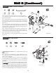
BAG D Step D-1 Cross Bone Coupler: 108 110 215 1. Apply a small amount of Thread Lock (119) to a 4-40 x 3/32 Set 107 Screw (108) and thread it into the Cross Bone Coupler (215). 3. Place the greased Cross Bone Coupler into the large hole of the Cross Bone. Align the hole in the Coupler with the slot in Cross Bone and insert the Cross Bone into the large end of the Rear Axle. 4.
READ THIS FIRST! 800-0226 STOP! The washers marked "Do Not Use" in the diagram, have been removed and should not be used under any circumstances. The parts are included in the assembly bags, and can be used in other applications, However, Do Not use the washers in this application. Step D-5 Rear Hub Install 119 1. Clean any dirt or oil off the screw by wipping the threads of the screw (111) on a rag. This will ensure that the Thread Lock (119) will stick to the threads of the screw. 2.
BAG D (Contin ued) (Continued) Step D-4 Wheel Hex and Lever Install: 117 1. Slide the Wheel Hex (112) over the Rear Axle (109). 2. Place the Retainer Spring (210) in the orientaion shown in Figure D-3, on previous page, with the Retaining Lever (211) between the legs of the Spring. Make sure the Spring is set into the groove on the Retaining Lever. 3.
BAG D (Contin ued) (Continued) Step D-6 Rear Pivot Set Screw Install: 134 134 1. Thread a 4-40 x 1/8" Set-Screw(134) into each hole on the bottom of the Rear Pivot Block (104). Just thread it in far enough to start the Set-Screw, it will be tightened in the next step.
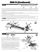
BAG E Step E-1 Diff Nut Assembly: Figure E-1A 58 57 59 58 1. Locate the 5/64" Allen Wrench (59) supplied with the kit. Place the Diff Nut(57), tab side first, over the Allen Wrench. 2. Stack 12 Belleville Washers (58) over the Wrench, next to the Diff Nut. The Washers should all point the same direction with the concave side facing away from the Diff Nut as shown in Figure E-1B. Figure E-1B Belleville washers should be stacked like this Step E-2 Male OutDrive Assembly: 60 1.
BAG E(Contin ued) E(Continued) Step E-4 Diff Gear Assembly: 63 63 65 65 1. Insert a 5mm x 8mm Bearing (63) into the center of the Diff Gear 64 (64). 2. Press a 3/32" carbide Diff Ball (65) into each of the 12 small holes in the Diff Gear. Figure E-4 Step E-5 Outdrive and Diff Gear Assembly: 64 65 CLEAR GREASE 1. Apply a small amount of clear Diff Grease (62) to cover Diff Balls on both sides of the Gear.
BAG E (Contin ued) (Continued) Step E-7 Diff Bearing Install: 63 63 61 61 1. Locate the 5/64" Allen Wrench (59) and place it through the slot in the Outdrive (66) containing the Diff Screw (67). Slide the Wrench all the way against the Screw. By handling the outdrive with the wrench inserted, the Diff Screw will be held in place while finishing assembly of the differential. 2. Insert a 5mm x 8mm Bearing (63) into the female Outdrive.
BAG E (Contin ued) (Continued) Step E-9 Compound Gear Assembly: 76 181 79 78 1. Locate the Brake Shaft (77) and press the .078" x 3/8" Spirol Pin 76 (78) into the small hole away from the grooved end of the Brake Shaft so that it extends evenly from both sides of the Shaft. 2. Press the Compound Gear Bushing (181) all the way into the end of the Compund Gear (79). Slide the Compound Gear, with the Bushing in place, over the Brake Shaft.
BAG E (Contin ued) (Continued) Step E-11 Left Gear Box Bearing Install: PRE-TAP THESE HOLES 80 81 83 1. Use the short, 4-40 Thread-Cutting Screw, included in the wrench bag, to pre-tap the three holes noted in Figure E-11. Thread the Screw all the way into and out of each hole on the Left Gearbox Half (83). 2. Insert two 3/16" x 3/8" sealed Bearing (80) into the two top bearing seats of the left Gearbox Half. 3.
BAG E (Contin ued) (Continued) Step E-13 Compound Gear Install: 80 1. Insert the Brake Shaft (77) through the 3/16" x 3/8" Bearing (80) 77 in the left Gearbox Half (83), aligning the teeth of the Compound Gear with those of the the Diff Gear (64) and Top Shaft (75). Push the the Brake Shaft through the Bearing. 83 79 64 Figure E-13 Step E-14 Gear Box Assembly: 85 86 87 83 82 1. Apply a thin coat of white Assembly Grease (71) to both sets of gears on the Compound Gear (79).
BAG E (Contin ued) (Continued) Step E-15 Slipper Clutch Assembly: 93 94 95 1. Slide the Slipper Backing Plate (89) over the Slipper Shaft (73), aligning the flat sections on the Slipper Shaft with the flat sections of the Slipper Backing Plate. Place a drop of glue to the Spur Gear before locating the slipper pad to the notches on the spur gear. This will make the assembly of slipper easier. 2.
BAG E (Contin ued) (Continued) Step E-16 Brake Hub Install: 27 96 97 120 1. Press the 2mm x 8mm Solid Pin (120) into the hole in the end of 120 the Brake Shaft (77) so that it extends evenly from both sides of the Shaft. 2. Slide the Brake Hub (98) over the Brake Shaft. Align the groove in the Brake Hub with the Pin and slide the Hub over the Pin. 3. Use the short, 4-40 Thread-Cutting Screw, included in the wrench bag, to pre-tap the three holes shown in Figure E-16. 4.
BAG E (Contin ued) (Continued) Step E-18 Brake Lever Assembly: 95 103 96 103 102 1. Place a 1/4" x .020 Washer (96) over each of the two 4-40 x 5/8" Set Screws (27) against the Brake Sleeve. 2. Hold the Brake Lever Clips (101) in position on the Brake Lever (102), slide the Brake Lever Clips over the 4-40 x 5/8" Set-Screws. IMPORTANT NOTE:Be sure the top Brake Lever Clip points towards the front of the Gearbox and the lower Brake Lever Clip points towards the rear. 3.
BAG E (Contin ued) (Continued) Step E-20 Rear Shock Tower Assembly: 35 33 35 33 38 123 1. Insert two 4-40 x 7/8" Cap-Head Screws (33), one on each side of the Rear Shock Tower (123), through the outer holes in the Rear Shock Tower. The Screw should point towards the rear of the truck as shown in Figure E-20. 2. Secure the 4-40 x 7/8" Cap-Head Screws in the Rear Shock Tower, by threading a 4-40 Nut (35) over each Screw and tightening.
BAG E (Contin ued) (Continued) Step E-22 Rear Camber Tierod Assembly: 54 124 There is a small Container/Package of White Grease used in Step E-6. It is reccomended that a small amount of this Grease be applied to the threads of the Turnbuckles before trying to thread on the Plastic Rod Ends. Please use this lube sparingly as its use is reccomended in later steps. *NOTE: The two ends of the turnbuckle are threaded opposite directions.
BAG E (Contin ued) (Continued) Step E-24 Battery Box Install: 9 31 36 123 1. Slide the Battery Box (125) into place on the back of the Chassis (19). The top flange of the Battery Box should fit between the Rear Shock Tower (123) and the Gearbox (82). The back of the Chassis should fit snug into the recess in the bottom of the Battery Box. Be sure that all the holes line up. 2. Place a gold Ball Stud Washer (9) over each of the 4-40 x 1/2" Cap-Head Screws (31).
BAG F Step F-1 Shock Assembly: 130 131 1. Place a drop of Shock Fluid (132) on the grooved end of each 130 131 Shock Shaft [front (130), rear (131)]. Then slide a Shock Shaft through the hex shaped end of the Shock Cartridge (114). Slide the Shock Shaft through until it is approximately midway between the threads and grooves, as shown in Figure F-1. 114 Figure F-1 Step F-2 Shock End Install: 133 121 121 IMPORTANT NOTE: Use caution when threading the Shock Shaft Ends onto the Shafts.
BAG F (Contin ued) (Continued) Step F-3 Shock Piston Install: 46 130 1. Before installing the E-clip to the front Shock Shafts- the shorter 131 of the two lengths, slide a Plastic Spacer (120) marked with a small "A" (0.120 Thick) over the front Shock Shaft next to the Cartridge. Once the Spacers are in place, snap a 1/8" E-clip into the groove closest to the Cartridge on both front Shock Shafts. *NOTE: Shock Spacers are only used on the front Shock Shafts in this step. 2.
BAG F (Contin ued) (Continued) Step F-5 Shock Adjustment Nut Assembly: *Note: This step will only be used for maintenance purposes. These come pre-assembled in the kit. 139 126 *NOTE: Place a drop of Shock Fluid onto each O-ring before installing it into the Shock Adjusting Nut.This will allow the Nut to thread onto the Shock Body easily. 1. Place the O-ring (126) into the grove inside of the Shock Adjusting Nut (139), Be sure to seat the O-ring completely into the groove as shown in Figure F-5B.
BAG F (Contin ued) (Continued) Step F-7 Rear Shock Install: 31 95 142 138 142 33 1. Make sure that the Cross Bones (107) are in the Outdrives (60)(66) before continuing. 2. Insert a 4-40x 1/2" Cap-Head Screw (31) through the Shock Mount Ball (121) in one of the rear Shocks. Position the bottom of the Shock, with the Screw, behind the the Shock mounting area on the left rear Suspension Arm (118).
BAG G Step G-1 Tire Mounting and Install: 116 114 149 214 150 1. Inspect the inside of the Tires [front (144), rear (145)] for any excess material. If present, trim excess rubber to ensure proper seating of the Tire bead onto the Wheel (147). During Tire assembly, make sure that all lettering on the sidewall of the front Tires faces to the outside of the Wheel. *NOTE: Do not set Tires on furniture as they may leave permanent stains.
BAG G (Contin ued) (Continued) Painting the Body and Wing BODY AND WING PAINTING Prepare the Lexan Body and Wing for painting by washing them thoroughly (inside and out) with warm water and liquid detergent. Dry both the Body and Wing with a clean, soft cloth. Use the supplied Window Masks (206) to cover the windows from the inside. A high-quality masking tape should be used on the inside of the Body to mask off any stripes, panels, or designs that you wish to paint on the Body or Wing.
Ba g H Bag Step H-1 Clutch Pin Install: 151 1. Remove any hardware that came installed on the crankshaft of your engine. This includes all nuts, washers, and prop hubs. *NOTE: If your engine did not come with a glow plug you will need to purchase one. Use a glow plug wrench, or a 5/16" nut driver to install the glow plug into the head of the engine. Most glow plugs come with a brass washer, and should be placed between the head of the engine and glow plug.
Ba g H Bag Step H-4 (Contin ued) (Continued) Clutch Shoe Install: IMPORTANT NOTE: Make sure that the Clutch Shoes are facing the correct direction as illustrated, when the motor has been installed. Position the Clutch so that the shoes are separated one on top, one on bottom. The top Clutch Shoe should be attached to the Pin at the left side of the Flywheel, as shown in Figure H-4, when looking at the engine from the front. 155 157 1. Slide the Clutch Shoe assembly over the Clutch Nut (155).
Ba g H Bag (Contin ued) (Continued) Step H-6 Engine Mount Install: 31 9 9 31 1. Place a Ball Stud Washer (9) over the four 4-40 x 1/2" Cap-Head Screws (31). Insert a 4-40 x 1/2" Cap-Head Screw through the four holes in the engine as shown. Use Thread-lock compound on the threads of the Screws for the Engine Mounts to prevent the Screws from backing out. 2. Attach the engine to the Engine Mounts (164) by threading the four Screws into the four holes shown.
Ba g H Bag (Contin ued) (Continued) Step H-8 Air Filter Install: 167 1. Press the paper Air Filter Element (165) into the large end of the Air Filter Boot (166). Be sure that the side of the Paper Element with the hole in it is inserted into the boot. 2. Slide the foam Pre-Filter (167) over the Paper Filter. 165 Air filter oil should always be applied to the foam PreFilter before running.Do not apply filter oil to the paper filter element. 3. Attach the Air Filter Boot to the carburetor.
Ba g H Bag Step H-10 (Contin ued) (Continued) Engine Install: 172 173 1. Place a Countersunk Washer (172) over each of the 5-40 x 1/2" Flat-Head Screws. 2. Position the engine in the Chassis (19) and line up the holes in the Engine Mounts (164) with the slots in the Chassis. IMPORTANT NOTE: Use a Thread-Lock compound on the threads of the screws in the Engine Mounts to keep them from coming loose. 3.
Ba g H Bag (Contin ued) (Continued) Step H-12 Tuned Pipe Install: 1. Place the silicone Exhaust Coupler (174) over the end of the Exhaust Header (171) as shown. 2. Insert the Tuned Exhaust Pipe (175) into the opposite end of the Exhaust Coupler so that the exhaust outlet on side of the Pipe points away from the truck, and the mounting stud points straight up. 171 174 175 Figure H-12 Step H-13 Pipe Mount Adjustment: 17 23 29 47 17 47 23 1 .
Ba g H Bag (Contin ued) (Continued) Step H-14 Coupler Tie Strap Install: 1. Secure the Tuned Pipe (175) to the Coupler (174) by wrapping an 8" Tie Strap (180) around the Coupler, and the pipe, and tighten. 2. Secure the Coupler to the Exhaust Header (171) by wrapping another 8" Tie Strap around the Coupler and Header and tighten. Cut off the extra length from both Tie Straps. 174 171 180 175 Figure H-14 Step H-15 Pressure and Fuel Line Install: 1. Cut an 10.
Ba g I Bag Step I-1 Receiver Install: For best results clean the surfaces that the Two-Sided Tape will be attached to with a mild rubbing alcohol. This will ensure a good, strong bond. Allow the surface to fully dry before attaching the Tape. 1. Cut a piece of Two-Sided Tape (182) to the same size as the bottom of the receiver (receiver not included). Remove the backing from one side of the Tape and attach it to the bottom of the receiver. 2.
BAG I (Contin ued) (Continued) Step I-3 Receiver Pack Install: 17 186 1. Place the battery pack into the Battery Box (125), so that the 17 power lead is to the right side of the Chassis. Cut two small pieces of the Battery Spacer Foam (185) to fit inside the Battery Box on each side of your battery pack. The foam should fit tightly between the battery pack and the sides of the Battery Box to prevent the battery pack from moving around inside the box while running your truck. 2.
BAG I (Contin ued) (Continued) Step I-5 Throttle Servo Install: 31 23 23 31 1. Attach the Grommets (supplied with your radio system) to the throttle servo per the radio system instructions. 2. Route the servo lead and plug through the slot in the bottom of the front Servo Mount (188) and plug it into the slot marked "Channel 2" in the receiver. 3.
BAG I (Contin ued) (Continued) Step I-7 Switch Install: 1. Remove the two small screws from the switch (supplied with radio system). Place the switch, from the bottom, into the Switch Mount (189), with the on position towards the front of the truck. 2. Place the switch top plate (if applicable) over the switch, on top of the switch mount. Line up the holes in the switch with the holes in the top plate and secure the switch to the Switch Mount with the two screws from the switch. 3.
BAG I (Contin ued) (Continued) Rotar y Valv e Carb ur etor s alve Carbur uretor etors If your engine comes equipped with a rotary valve carburetor, complete the steps in Figure I-9 through Figure I-15. If your engine comes equipped with a slide valve carburetor, skip ahead to page 48 and complete the steps in Figure I16 through Figure I-22. Step I-9 Throttle Z-Bend Assembly: 193 193 192 1.
BAG I (Contin ued) (Continued) Rotar y Valv e Carb ur etor s alve Carbur uretor etors Step I-11 Rotary Carb Servo Arm: 190 1. For rotary valve carburetors, you will need to remove the straight, shorter arm of the Throttle Servo Arm (190), as shown in Figure I-11. Cut off the Arm with heavy duty clippers or a DremelTM hobby tool. Figure I-11 IMPORTANT NOTE: Follow all cutting tool manufactures warnings and wear eye protection. Step I-12 Servo Insert Install: 1.
BAG I (Contin ued) (Continued) Rotar y Valv e Carb ur etor s alve Carbur uretor etors Step I-14 Brake Collar Install: 192 193 102 193 1. Install the Throttle Linkage Z-bend wire (191) in the top hole of the Throttle Servo Arm so that the wire is positioned on the side of the Arm toward the engine. 2. Ensure the serve is centered by turning the radio and receiver to the on position, before proceeding. 3.
Ba g I Bag (Contin ued) (Continued) Slide Valv e Carb ur etor s alve Carbur uretor etors NOTE: If your engine comes equipped with a slide valve carburetor, complete the steps in Figure I-16 through Figure I-22. Step I-16 Throttle Linkage Assembly: 193 193 192 1. Thread the 4mm Ball Cup (204) all the way onto the end of the 195 204 Threaded Throttle Rod (203). Slide a Linkage Collar (192) over the other end of the Throttle Rod, and up against the Ball Cup.
Ba g I Bag (Contin ued) (Continued) Slide Valv e Carb ur etor s alve Carbur uretor etors Step I-18 Slide Carb Servo Arm: 190 1. For slide valve carburetors, you will need to remove the shorter, perpendicular Arm of the Throttle Servo Arm (190), as shown in Figure I-18. Cut off the Arm with heavy duty clippers or a DremelTM hobby tool. Figure I-18 IMPORTANT NOTE: Follow all cutting tool manufactures warnings and wear eye protection. Step I-19 Servo Insert Install: 1.
Ba g I Bag (Contin ued) (Continued) Slide Valv e Carb ur etor s alve Carbur uretor etors Step I-21 Brake Collar Install: 193 192 193 102 1. Snap the 4mm Ball Cup (204) onto the ball on the carburetor. Make sure the ball is pointing toward the right side of the truck and slightly upward. 2. Ensure the serve is centered by turning the radio and receiver to the on position, before proceeding. 3.
BAG I (Contin ued) (Continued) Step I-23 Throttle Linkage Adjustment: 1. Turn your transmitter switch on followed by the receiver switch (or plug in the extension wire if not using a switch). 2. With the throttle control on the transmitter in the neutral position and the trim centered, check to make sure the carburateor opening is in the fully closed position. Adjust the position of the collar (192) along the throttle wire until there is a 0.020" gap between the override slider(195) and collar.
Ba g I Bag (Contin ued) (Continued) Step I-24 Air Filter Install: 165 1. Turn the radio switch off, and then turn the transmitter off. Make it a habit to always turn the transmitter on first and off last. 2. Once the throttle and brake linkages are adjusted, replace the Air Filter (165) in the Air Filter Boot (166).
FINAL CHECKLIST BEFORE RUNNING YOUR XXX-NT AD2 for the first time, you should run down the following checklist — in order — and complete the listed tasks. This simple checklist will help to make the first run with your new XXX-NT AD2 truck much more enjoyable. 1. Adjust the rear differentialNever let your Differential Slip! See Adjusting The Differential in the tips section. 2.
Tips and P ar ts (Contin ued) Par arts (Continued) found at most hobby shops. This can also help prevent glitching and increase the life of your receiver and is the reccomended method most the team racers. The objectof the receiver cover is to completely cover all openings and crystal socket to keep water or fuel out. Any liquid that enters the receiver can cause radio failure, keep the receiver dry. THE CLUTCH BEARINGS included in the kit contain a special lubricant.
Tips and P ar ts (Contin ued) Par arts (Continued) back off the adjustment nut 1/8 of a turn and retry. If you can’t hear the slipper when you punch the throttle, hold the front of the truck with the rear wheels still on the track and give the truck full throttle. The truck should push against your hand with reasonable force and the slipper only slipping slightly. Don't expect the slipper to make up for poor driving or set-up. You still have to use the throttle and maintain the shocks and chassis.
Tips and P ar ts (Contin ued) Par arts (Continued) The bottom of the shock can also be moved in or out on the suspension arm. Moving the bottom of the shocks to the inside hole in the arm will result in more low-speed steering and less high-speed steering. Mounting the shocks in the inside hole will require limiters in the shocks to limit the travel, and the springs should be changed to stiffer ones.
SP ARE P AR TS LIST SPARE PAR ARTS KEY # 1 2 3 4 5 6 7 8 9 10 11 12 13 14 15 16 17 18 19 20 21 22 23 24 25 26 27 28 29 30 31 32 33 34 35 36 37 38 39 40 41 42 43 44 45 46 47 48 49 50 51 52 53 54 55 56 57 KIT/PART DESCRIPTION Servo saver bottom Servo saver post Servo saver top Servo saver spring Servo saver spring cap 6-40 locknut 4-40 mini locknut Steering idler arm Ball stud washer 1/4" Ball Stud 3/16" Ball Stud Steering drag link 3/32" x 3/16" ball bearing Front Kickplate Steering brace 3/32" x .
SP ARE P AR TS LIST SPARE PAR ARTS KEY # 58 59 60 61 62 63 64 65 66 67 68 69 70 71 72 73 74 75 76 77 78 79 80 81 82 83 84 85 86 87 88 89 90 91 92 93 94 95 96 97 98 99 100 101 102 103 104 105 106 107 108 109 110 111 112 113 114 KIT/PART DESCRIPTION Concave Diff Washers Allen wrenches Male outdrive Drive ring Clear diff grease 5mm x 8mm bearing 55 tooth diff gear 3/32" diff balls Female outdrive Diff screw Foam diff seal Thrust washer 5/64" Caged thrust assembly White thrust bearing grease 3/8" Short head ba
SP ARE P AR TS LIST SPARE PAR ARTS KEY # 115 116 117 118 119 120 121 122 123 124 125 126 127 128 129 130 131 132 133 134 135 136 137 138 139 140 141 142 143 144 145 146 147 149 150 151 152 153 154 155 156 157 158 159 160 161 162 163 164 165 166 167 168 169 170 171 172 KIT/PART DESCRIPTION Rear arm bushing 2-56 x 1/2" Button-head screw 1/16" x 1/2" Drive pin Rear Arm, Left Thread lock 2mm x 8mm Drive pin Shock mount ball Rear inner hinge pin Shock tower, rear 3.
SP ARE P AR TS LIST SPARE PAR ARTS KEY # 173 174 175 176 177 180 181 182 183 184 185 186 187 188 189 190 191 192 193 194 195 196 197 198 199 200 201 202 203 204 205 206 207 208 209 210 211 212 213 214 215 KIT/PART DESCRIPTION 5-40 x 1/2" Flat-head screws Silicone exhaust coupler tubing Tuned pipe Fuel tubing Pipe mounting bracket 8" tie-strap Compound gear bushing Two-sided tape (thick) Antenna tube Antenna cap Battery spacer foam Battery box lid 2-56 x 1/2" Button head screw Throttle servo mount Switch mo