
User Manual


BB
BB
B
AA
AA
A
G G
G G
G
AA
AA
A
1
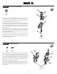
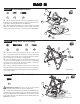
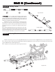
Step A-1
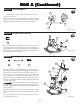
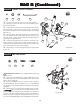
Step A-2
1. Place the Servo Saver Bottom (1) over the Servo Saver Post
(2) and slide the Servo Saver Bottom all the way against the hex at
the opposite end. Be sure that the hex on the Servo Saver Post is
inserted into the hex in the Servo Saver Bottom.
2. Slide the Servo Saver Top (3) down over the Servo Saver Post
so that the 'V' area of the Servo Saver Top rests in the 'V' area of the
Servo Saver Bottom. The arm on the Servo Saver Top and the arm on
the Servo Saver Bottom should now point in opposite directions as
shown in Figure A-1.
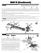
3. Slide the Servo Saver Spring (4) over the Servo Saver Post
and push it into the recessed area of the Servo Saver Top. Install the
Servo Saver Spring Cap (5) and thread the 6-40 Locknut (6) onto the
end of the Servo Saver Post.
4. Tighten the 6-40 Locknut all the way down and then loosen it
two full turns (e.g. 360
o
x 2). This is a good starting point for the
adjustment. Once assembly is complete, if you wish, the servo saver
can be adjusted tighter or looser.
1. Insert a 4-40 Mini-Locknut (7) into the outer hex area in the
Servo Saver Bottom (1) and steering Idler Arm (8) as shown in Fig-
ure A-2. Thread a 3/16" Ball Stud (11) through the outside hole in the
Servo Saver Bottom and steering Idler Arm and into the Nuts, and
tighten. Insert a 4-40 Mini-Locknut into the hex area, on the under-
side of the Servo Saver Top (3). Thread a 3/16" Ball Stud through the
hole in the Arm, into the Nut, and tighten.
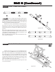
2. Insert a 4-40 Mini-Locknut into the hex areas in the rear holes
of the Servo Saver Bottom and the steering Idler Arm as shown in
Figure A-2. Thread a 3/16" Ball Stud through the Arms, into each
Nut, and tighten.
Figure A-1
Figure A-2
Servo Saver Assembly:
Ball Stud Install:
2
3
4
5
1
6
8
3
7
7
1
11
6
7
11