
User Manual

13
14
15
16
17
8
18
14
BB
BB
B
AA
AA
A
G G
G G
G
A (ContinA (Contin
A (ContinA (Contin
A (Contin
ued)ued)
ued)ued)
ued)
2
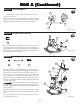
Step A-4
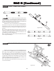
1. Install a Threaded Insert (18) into the top of each of the two
forward holes in the front Kickplate (14). The inserts should be in-
stalled with the hex-side up as shown in Figure A-4. Press the Threaded
Inserts all the way into the holes in the Kickplate, lining up the hex on
the inserts with the hex in the holes.
Figure A-4
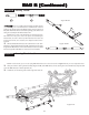
Figure A-5
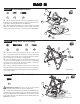
Step A-5
18
Threaded Insert Install:
1. Insert a 3/32" x 3/16" Ball Bearing (13) into each of the two,
angled holes in the bottom of the front Kickplate (14). Insert the other
two Bearings into the two outer holes in the Steering Brace (15).
2. Insert a 3/32" x .930" Hinge Pin (16) through the hole in the
steering Idler Arm (8) and center the Hinge Pin in the Idler Arm.
Place the Servo Saver assembly and the steering Idler Arm into the
Bearings in the Kickplate so that the installed Draglink is to the front
as shown in Figure A-5.
There is a short Thread-Cutting Screw included in the
Wrench bag. This Screw can be used to tap threads in the holes in the
Kickplate. Pre-tapping these holes makes it easier to install the Screws
during assembly.
3. Place the Steering Brace on top of the Servo Saver assembly
and steering Idler Arm ensuring that the Ball Bearings slide over the
Pins.
4. Secure the Steering Brace to the Kickplate using two 4-40 x
3/8" Cap Head Screws (17).
Steering Install:
13
17
16
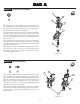
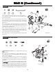
Step A-3
*NOTE: Be sure to snap each end of the Draglink onto the cor-
rect Ball Stud as shown!
1. Snap one end of the steering Draglink (12) onto the rear Ball
Stud (11) on the Servo Saver Bottom (1). Snap the other end of the
Draglink onto the rear Ball Stud on the steering Idler Arm (8).
Servo Draglink:
Figure A-3
12
11
1
8
11