
User Manual


14
20
38
32
9
34
17
32
BB
BB
B
AA
AA
A
G BG B
G BG B
G B
3
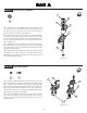
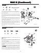
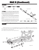
Step B-2
Figure B-1
Figure B-2
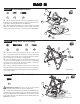
Step B-1
Front Bulkhead Install:
Front Shock Tower Assembly:
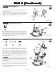
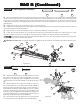
Front Shock Tower Install:
Figure B-3
Step B-3
17
7
IMPORTANT NOTE: The Screws in the top of the Shock
Tower must be pointing forward as shown in Figure B-3.
1. Attach the front Shock Tower (34) to the front Bulkhead (32)
with four 4-40 x 3/8" Cap Head Screws (17). The Screws thread into
the top and bottom holes in the Bulkhead, corresponding with the
appropriate holes in the front Shock Tower. The middle holes in the
Bulkhead are not used.
1. Insert two 4-40 x 7/8" Cap Head Screws (33) — one on each
side — through the second hole out (#2 hole) in the top of the front
Shock Tower (34). Secure the Screws to the Shock Tower by thread-
ing a 4-40 Nut (35) over each Screw and tightening.
2. Press a 4-40 Mini Locknut (7) into the hex area in the top, rear
of each side of the front Shock Tower. Insert a 4-40 x 1/2" Flat Head
Screw (36) into each of the two front Body Mounts (37) from the
side with the recess for the head of the Screw.
3. Attach a front Body Mount to the front of each side of the
front Shock Tower so that the posts point up as shown in Figure B-2.
Secure the Body Mounts by threading the Screws through the Tower
and into the Locknuts.
1. Secure the front Kickplate (14) to the front Bulkhead (32) by
threading a 4-40 x 3/8" Flat Head Screw (20) through the center hole
in the front of the Kickplate and into the Bulkhead.
2. Place one Ball Stud Washer (9) over each of the two 3/8" Ball
Studs (38). Thread the 3/8" Ball Stud into the outside of the three
camber position holes (#3 hole), on each side of the front Bulkhead.
9
20
38
34
35
36
7
33
37
36
35
33