
User Manual


46
48
46
52
49
51
50
43
72
53
49
14
32
52
75
21
BB
BB
B
AA
AA
A
G B (ContinG B (Contin
G B (ContinG B (Contin
G B (Contin
ued)ued)
ued)ued)
ued)
5
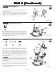
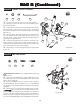
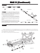
Figure B-7
Step B-7
1. Place the left Spindle and Carrier assembly (Figure B-6) into a front suspension Arm (48) as shown in Figure B-6. Note that the Spindle
Arm faces the side of the suspension Arm with the Shock mount holes (rear) and the Ball Stud (72) in the Spindle Carrier is pointing forward.
Line up the two sets of holes in the left Spindle Carrier (43) with the holes in the front Arm. Install a 1/8" E-clip (46) on one end of each 1/8"
x .960" Hinge Pin (50) and slide it through the outer-most of the two holes in the Arm and Spindle Carrier. Attach a 1/8” E-clip to the other side
of the Hinge Pin.
2. Install a 1/8" E-clip on one end of each inner 1/8" x 1.42" Hinge Pin (51).
3. Attach the Arm to the left side of the front Pivot Block (49) by inserting Hinge Pin from the back side, through the inside hole in the front
Arm and Pivot Block, as shown in Figure B-6.
4. Repeat Steps 1-3 for the right Spindle and Carrier assembly and remaining front suspension Arm.
5. Slide the front Hinge Pin Brace (52) over both front inner Hinge Pins with the flat side pointing down. The E-clip grooves in both
Hinge Pins should be exposed in front of the Brace. Secure the Brace by installing a 1/8" E-clip to the front of each Hinge Pin.
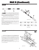
The XXX-NT AD2 has been designed with Variable Length Arms (VLA). For a more detailed description of the VLA system,
please read the VLA section in the back of this manual.
IMPORTANT NOTE: Make sure that the Hinge Pin is installed into the outer-most hole for both the VLA Arms and Spindle Carriers.
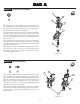
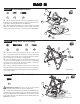
Step B-6
Figure B-6
Front Suspension Assembly:
1. Hold the Chassis assembly upside down. Place the front Pivot
Block (49) over the front edge of the front Kick plate (14) as shown
in Figure B-7. The front edge of the front Bulkhead (32) should be
positioned between the front Pivot Block and the Hinge Pin Brace
(52).
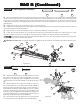
2. While holding the front suspension assembly in place, posi-
tion the front Bumper (53) on the bottom of the front Pivot Block so
that the four holes in the Bumper are aligned with the four holes in
the Pivot Block. The Bumper should be attached as shown so that the
edges curve towards the top of the Chassis. Secure the Bumper and
Pivot Block to the front Bulkhead and Kickplate by threading two 4-
40 x 5/8" Flat Head Screws (21) through two forward-most holes in
the Bumper and Pivot Block and into the Bulkhead.
3. Thread the two 4-40 x 7/8" Flat Head Screws (75) through the
two remaining holes in the front Bumper and into the Bulkhead.
Front Suspension Install:
21
75
46
51
50