
User Manual


Thank you for purchasing a Team Orion Brushless ESC. This ESC features the latest brushless technologies.
Our World Championship winning development team has spent countless hours developing this ESC so that
you can experience ultimate performance.
Please read these instructions thoroughly before using the ESC.
FEATURES
• Designed for on-road and off-road use
• High precision speed and power control
• High power built-in BEC system for stable receiver and servo power supply
• Easy set-up via the setup button or optional digital program box
• Forward and reverse function
• Several adjustable parameters (see list on separate sheet)
• Multiple protection systems: battery low voltage cut-off, overheating, radio signal loss, stuck motor
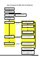
ESC AND MOTOR CONNECTION (see picture on separate sheet)
Sensorless brushless motor (all ESC types)
When using a motor without sensors, the A-B-C wire order is not important, if the motor spins in the wrong direction,
simply reverse two of the wires.
Sensor brushless motor (select ESC types only)
When using a motor equipped with sensors, a sensor cable must be used to connect the motor to the ESC. The ESC
detects when a sensor cable is connected and switches to sensor mode.
WARNING! When using sensor equipped motors, you must respect the A-B-C wire connection order when
connecting the motor to the ESC, you can’t connect the wires randomly.
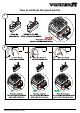
ESC CALIBRATION (see pictures on separate sheet)
In order to ensure proper function, the ESC must be calibrated to your transmitter inputs. It is recommended to center
the trims and reset all settings inside the transmitter before proceeding to the calibration.
Follow the procedure below to calibrate your ESC
A) Switch off the ESC and switch the transmitter on, set the throttle trim to neutral and set the throttle travel range to
100%”. Disable any special functions such as ABS, etc.
B) Press and hold the “SET” key (located on the switch or ESC), then switch on the ESC. Release the “SET” key as
soon as the red LED starts to flash.
C) Calibrate the throttle points by pressing the set button once after each step.
1. neutral point (1 flash)
2. full throttle (2 flashes)
3. full brakes/reverse (3 flashes)
D) The motor will run 3 seconds after the last step is completed.
STATUS LED FUNCTION
• In the neutral position, no LED are lit
• The red LED lights when the car is moving forward, backwards or is braking.
AUDIO WARNING TONES
1. Input voltage problem: ESC checks the input voltage as it is switched on, if a problem is detected, the ESC emits
repeatedly two beeps with a 1 second pause (xx-xx-xx).
2. Radio signal problem: ESC checks the radio signal input as it is switched on, if a problem is detected, the ESC
emits repeatedly a beep with a 2 second pause (x-x-x).
ESC ADVANCED SETUP
You can adjust several parameters by using the setup button located on the switch or ESC or by using the optional
digital program box (ORI65150).
Please note that depending on the ESC type you have purchased, the number of adjustable parameters may vary
(check the separate sheet for more information).
To adjust the parameters using the setup button, follow the procedure below (see picture on separate sheet).
A) Switch on the ESC.
B) Press and hold the setup button for one second until the green led starts flashing and then release the setup
button (holding the setup button for 5 seconds will restore the ESC to factory defaults).
C) Press the setup button once more.
D) The green LED blinks once repeatedly indicating that parameter nr.1 is currently selected.
E) By pressing on the setup button once more, you move to parameter nr.2 and so on until you have gone
through all the parameters. The process goes in a loop.
F) To change a parameter value, press and hold the setup button for 3 seconds while the green LED is flashing
the number of times corresponding to the parameter you wish to modify.
G) The red LED will flash indicating the actual setting. One flash means setting nr.1 is actually selected, two
flashes means setting nr.2 and so on.
H) Press the setup button to select the setting you wish to use for the current parameter. The process goes in a
loop.
I) Once you have selected the setting you wish to use, press and hold the setup button for 3 seconds to save the
change.
J) Switch the ESC off and back on to make the parameter change effective.
Please note : you can only change one setting at a time, after each modification you need to switch the ESC
off and back on both to make the parameter change effective and be able to modify another parameter.
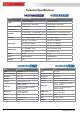
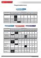
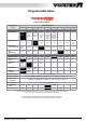
PARAMETERS
Running Mode
1)“Forward Only with Brake” this mode is meant for competition use. In this mode the car can go forward and brake,
there is no reverse.
2)“Forward/Reverse with Brake” this is the basic all-around mode. In this mode the car can go forward and reverse
and can also brake. When you move the throttle to the reverse position while the car is moving forward, brakes are
applied until the car is fully stopped, reverse cannot engage while the car is moving. To engage reverse, once the car
has stopped, release the brakes and move the throttle to the reverse position again.
While braking or in reverse, if the throttle is moved to the forward position, the car will immediately accelerate forward.
3)“Forward/Reverse” this mode is meant for Rock Crawler use. In this mode there is no brake, the car can go from
forward to reverse immediately without any pause. Do not use this mode with other car types as it can overload and/or
damage the ESC.
Drag Brake Force
Sets the amount of brake automatically applied when the throttle is returned to the neutral position. This simulates the
engine breaking effect of a real car, it can help improve turn-in and the general feeling of the car.
Low Voltage Cut-off
This function helps to prevent battery over-discharge. The ESC continuously monitors the battery’s voltage. If the
voltage becomes lower than the threshold for 2 seconds, the output power is shut off and the red LED flashes twice
repeatedly.
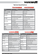
The cutoff threshold calculation is based on LiPo individual cell voltage. For NiMH batteries, if the voltage battery pack
is higher than 9.0V, it will be considered as a 3 cell LiPo battery pack; If it is lower than 9.0V, it will be considered as a
2 cell LiPo battery pack. Example: for a 8.0V NiMH battery pack used with a 2.6V/cell threshold, it will be considered
as a 2 cell LiPo battery pack and the low-voltage cut-off threshold will be 5.2V (2.6x2=5.2).
Using the optional Digital Program box (ORI65150) you can adjust custom values for the cutoff threshold. Unlike the
preset values, custom cutoff values are for the total battery voltage not individual cell voltage.
8 www.teamorion.com
ENGLISH