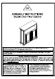
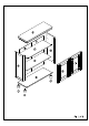
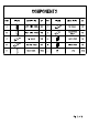
COMPONENTS PART FIGURE DESCRIPTION | GTY | PART FIGURE DESCRIPTION LEFT SIDE PANEL| 1pc | F & TOP PANEL | 1PC B H RIGHT SIDE PANEL| 1PC FIX SHELF | 1PC | H @ LEFT DOOR | 1PC b & BOTTOM SHELF | 1pC @ RIGHT DOOR | 1PC E D BACK PANEL | 2PCS| J & LEG PCs
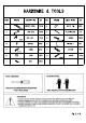
HARDWARE & TOOLS PART FIGURE DESCRIPTION | QTY | PART FIGURE DESCRIPTION | @QTY 1 \ WOODEN DOWEL | PCs | 8 % SHELF PIN | PCS 8430 2 6@ CAM BOLT | 12PCS| 9 \ PLASTIC BAR | 1PG 3 @ CAM LOCK PCs | 10 %@ SCREW PCS #1549 212 D=7 4 WASHER wes | 12 g FIX BELT 1PG 5 o SCREW T ANCHOR 1pc $3%12 % 6 © KNOB PCs | 14 SCREW PCs 7 R, BOLT PCS TOOL NEEDED: SUGGESTION: PHILIPS SCREWDRIVER REQUIRED i q « HOT INCLUDED TWO PEOPLE FOR ASSEMBLING WARNINGS:! 1. BO NOTELET ANY BARR OBJECT TOUCH DR BUS THE SURFACE OF THE PRODUCT.
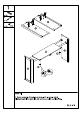
STEP 1: 1. Screw cam bolts (2} and insert dowels (1) in panels Attach panel C to panels A & B and secure with cam locks (3).
STEP 2: 1. Screw leg J to panel D. 2. Screw cam bolts (2) and insert dowels (1) in panel D. 3. Attach panel D to panels A & B and secure with cam locks (3).
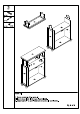
4 PGS 2 4 PcS 3 @‘Q 4 PCS 91549 STEP 3: 1. Screw cam bolts (2) in panel F. 2. Insert dowels (1) in the tops of panel A&B. 3. Attach panel F to panel A&B and secure with hammerlock.
STEP 4: 1. Attach panels E to the back of the cabinet and secure with screws {10) as shown. 2. Insert plastic bar (9) as shown and finish securing panels E with screws (10).
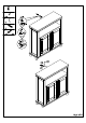
STEP 5: 1. Attach knobs (6) to doors H & | with bolts (7). 2. Attach doors the cabinet with screws (5). 3. Insert shelf pins (8) into panels Rest adjustable shelf G on the shelf pins.