
Datasheet


General Purpose
Series
■ Features: 105℃ 1000 hours
SH
■ Recommended Applications: For general purpose coupling,decoupling ,
Lon
g
Lif
e
by pass , and filtering circuit in entertainment electronics
SE
■Corresponding product to RoHS
■ Specifications
Rated Capacitance Range
Capacitance Tolerance
(After rated voltage applied for 2 minutes )
6.3 10 16 25 35 50 63~100 160~250 350~450
0.26 0.22 0.18 0.16 0.14 0.12 0.10 0.15 0.20
8653371015
1086437——
the capacitors shall meet the following requirements.
the capacitors shall meet the same requirement as Endurance.
■ Diagram of Dimensions
ψD
5 8 10 13 16 18
P 2.0 3.5
ψd
0.5
0.6
a 1.5
1.5
1.5 2.0 2.0 2.0
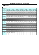
■ Multiplier for Ripple Current
Frequenc
y
coefficient
1 ~ 150μF1 ~ 15000μF 1 ~ 470μF
I=0.01CV or 3(μA) ,whichever is greate I=0.03CV+10(μA)
WV
Z(120Hz)
1K
1.30
Dissipation Factor
Low Temperature Stability
WV
tanδ
Z-25℃ / Z+20℃
When nominal capacitance is over 1000uF,
tanδ shall be added 0.02 to the listed value with increase of every 1000uF。
10.0
0.8
7.5
Z-40℃ / Z+20℃
Within ± 20 % of initial valueCapacitance Change
2.5
6.3
5.0
350 ~ 450VDC6.3 ~ 100VDC 160 ~ 250VDC
After applying rated voltage for 1000 hours at 105℃
Not more than 200% of the specified value
22
120
0.5
1.5
300
0.6
Characteristics
-25~+105℃ -40~+105℃ -40~+105℃
Item
6.3 ~ 100V 100 ~ 680μF
6.3 ~ 100V 1000 ~ 22000μF
Rated Voltage Range
Endurance
Frequency (Hz)
Operating Temperature Rang
e
Dissipation Factor (MAX)
(tanδ) (120Hz ,20℃)
6.3 ~ 100V Below 68μF
1.05
1.10
1.00 1.20
1.00
1.00
1.00
ALUMINUM ELECTROLYTIC CAPACITOR
S
Shelf Life
Leakage Current (MAX)(20℃)
After leaving capacitors under no load at 105℃ for 500 hours.
Leakage Current
Impedance Ratio (MAX)
16 25
SE
10K
1.50
1.15
1.10
1.25
1.15
2.0
± 20 % at 120Hz , 20℃
35~100 160~250 315~350 400~4506.3 10
initial specified value or less
0.8
160 ~ 450V ALL Cap (μF)
1.45
1.05 1.10