
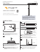
Installation Sheet

2
4
5
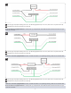
Connect the red and black wires from the column top
respectively to the red and black wires in the column
base by inserting them into an open port in wire
connectors. Close the levers to lock the wires in place.
Connect the fixture to a suitable ground in accordance
with local electrical codes.
Connect the neutral power line wire to terminal block
connected to the white wires.
Connect the hot power line wire to terminal block
connected to the black wires.
Use the gray and purple dimming wires for 0-10v
dimming application (if not in use, make sure to cap
these wires off).
Reinstall the access panel (reversal of section 2A).
6
7
Warning: The purple and gray wires are only used for 0-
10v dimming. For all other applications, do not connect
the gray and purple wires.
8
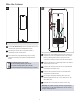
2A
Loosen the access panel set screw on(Do Not Remove)
column base with the provided Allen wrench.
Pull away the top of the access panel and lift it
completely out the column base.
Power the fixture using the following steps or wiring
diagrams according to the options included with the
fixture.
1
2
Wire the Column
5
6
7
8
4
4
2B
9
For Standard options, go to step 2B.
For Photocell/Surge options, go to step 2C.
For In-line Fuse/Surge options, go to step 2D.
For Photocell/In-line Fuse/Surge options, go to step 2D.
3