
Installation Sheet

2
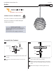
For power connection, leave at least 6" of the cord
exposed in the back of the canopy.
Cut off the excess cord with a sharp cutter.
From the end of the cord, strip the outer insulation 4"
using a sharp knife and needlenose pliers. Make sure
not to cut inner wires.
Strip 1/4" of insulation from the inner insulated wires.
(three inner insulated wires for standard SVT cord). The
bare inner wire is the ground wire (green insulated wire
in SVT cord).
4"
6
7
8
9
6
7
1C
1D
8
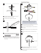
Install the Fixture
Connect the fixture bare uninsulated wire to the ground
in accordance with local electrical codes.
Connect the insulated pendant wire to each of the red
driver wires.
Connect the white driver wire to the neutral power line
wire.
Connect the black driver wire to the hot power line
wire.
Place all wires, wire nut connections, and the driver
properly inside the canopy.
Mount the canopy to the electrical box with two #8-32
screws provided.
#8-32 SCREW
2A
1
2
3
2
2
1
DRIVER
4
3
4
2B
5
6
6 6
5
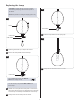
NOTE: If the canopy mounting holes do not match
up with electrical box, install the provided universal
mounting plate before making wire connections.