
Installation Instructions

1.0
Installation Instructions for
700WSTMB
1
2
1
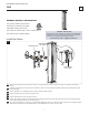
Remove the mounting plate from the fixture base by unscrewing the Allen screws on the sides of the base using the provided Allen
wrench.
Install the mounting plate to the junction box with the two #8-32 screws (not shown) provided. Verify that the mounting plate is level
before continuing.
Connect the fixture to a suitable ground in accordance with local electrical codes.
Connect the white driver wire to the neutral power line.
Connect the black driver wire to the hot power line.
Properly place all wires and wire nut connections into the fixture base, then mount the fixture base back onto the mounting plate and
secure it by installing the Allen screws (reversal of step 1).
The arms may be adjusted. To achieve this, loosen ) the set screw on both ends of the respective arm using the provided(do not remove
Allen wrench, adjust the arm to the desired position, and re-tighten the set screws to secure in place.
1A
Install the Fixture
4
3
6
5
CAUTION RISK OF FIRE-
This product must be installed in accordance with the applicable
installation code by a person familiar with the construction and
operation of the product and the hazards involved.
Use minimum 90°c supply conductors.
7
4
ALLEN WRENCH
AND SCREW
MOUNTING PLATE
GP I :ENERAL RODUCT NFORMATION
This product is suitable for damp locations.
These fixtures are intended to be installed
utilizing NEC compliant junction boxes.
This product can be dimmed with most ELV or TRIAC dimmers.
This instruction shows a typical installation.
5
3
ARM
ALLEN WRENCH
& SET SCREW
7
Wall