
Installation Instructions

1.0
1
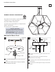
GP I :ENERAL RODUCT NFORMATION
This product can mount to either a 4” square electrical box with a
round plaster ring or an octagon electrical box.
This product is suitable for damp locations.
This product may be dimmed with a low-voltage electronic
dimmer or triac dimmers.
This instruction shows a typical installation.
1
CAUTION RISK OF FIRE-
This product must be installed in accordance with
the applicable installation code by a person familiar
with the construction and operation of the product
and the hazards involved.
Use minimum 90°c supply conductors.
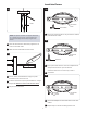
1A
Loosen the set screw on the strain(Do Not Remove)
relief.
Remove the crossbar from the canopy by completely
unscrewing the strain relief.
2
1
SET SCREW
STRAIN RELIEF
CANOPY
1
2
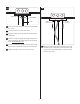
Shorten the Power Cord
Feed the aircraft cable through the cable clutch in the
canopy.
Pull the aircraft cable up through the canopy to
determine the fixture height.
Cut off the excess aircraft cable leaving enough for fine
leveling later.
Pull the power cord through the canopy to the desired
length.
AIRCRAFT
CABLE
CABLE
CLUTCH
STRAIN RELIEF
POWER CORD
CANOPY
1B
6
4
5
3
3
6
5
MOUNTING
PLATE
Installation Instructions
700TDHEX_