
User Guide


Installing System Components 107
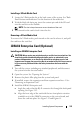
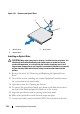
Figure 3-15. Removing and Replacing the Fan Assembly
Replacing the Fan Assembly
1
Being careful not to pinch the cables connected to the backplane board,
replace the fan assembly in the chassis, and close the two latches to secure
the assembly.
2
Connect each fan’s power cable to the power connectors on the system
board.
1FAN1 2FAN2
3FAN3 4FAN4
5 FAN5 6 FAN6 (dual-processor configurations
only)
7 fan power cables (6) 8 fan power connectors (6)
9 fan assembly latches (2) 10 fan blank (must be installed in single
processor configuration for proper
cooling airflow)
2
3
4
5
6
7
1
8
9
10