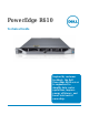
PowerEdge R610 Technical Guide Inspired by customer feedback, the Dell PowerEdge R610 server is engineered to simplify data center operations, improve energy efficiency, and lower total cost of ownership.
Dell This document is for informational purposes only. Dell reserves the right to make changes without further notice to any products herein. The content provided is as is and without express or implied warranties of any kind. Dell, the Dell logo, PowerEdge, and ReadyRails are trademarks of Dell, Inc. Citrix and XenServer are registered trademarks of Citrix Systems, Inc. and/or one or more of its subsidiaries, and may be registered in the United States Patent and Trademark Office and in other countries.
Dell Table of Contents 1 2 3 4 5 Product Comparison ........................................................................................... 7 1.1 Overview .................................................................................................. 7 1.1.1 Strong IT Foundation............................................................................... 7 1.1.2 Purposeful Design .................................................................................. 7 1.1.
Dell 5.9 Acoustics ................................................................................................ 24 Processors ..................................................................................................... 25 6.1 Overview ................................................................................................ 25 6.2 Features ................................................................................................. 26 6.3 Supported Processors .........................
Dell 12.4.4 PERC H700 ......................................................................................... 42 12.5 Optical Drives ........................................................................................... 43 12.6 Tape Drives ............................................................................................. 43 12.7 External Storage Support ............................................................................. 43 13 Video ................................................
Dell Table 20. Table 21. Ergonomics, Acoustics and Hygienics............................................................. 59 Industry Standards .................................................................................. 60 Figures Figure 1. Figure 2. Figure 3. Figure 4. Figure 5. Figure 6. Figure 7. Figure 8. Figure 9. Figure 10. Figure 11. Figure 12. Figure 13. Chassis Dimensions .................................................................................. 15 Front View .....................
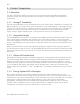
Dell 1 Product Comparison 1.1 Overview The Dell™ PowerEdge™ R610 is a 2-socket 1U rack server that offers simplified management, purposeful design, and energy efficiency that can help you better manage your enterprise IT environment. 1.1.1 Strong IT Foundation The Dell PowerEdge R610 is a key building block for today’s data center.
Dell 1.1.5 Simplified Systems Management With the optional advanced embedded systems management capabilities of Lifecycle Controller, Dell provides comprehensive enterprise class manageability already on the motherboard. Lifecycle Controller is delivered as part of the optional iDRAC Express or iDRAC Enterprise in the PowerEdge R610.
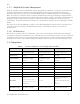
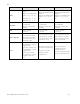
Dell Feature R510 R610 R710 External Drive Bay(s) Four- and eight-drive chassis: optional internal SATA slimline optical drives such as DVD-ROM or DVD+RW Twelve-drive chassis: N/A Optional internal SATA slimline optical drives such as DVD-ROM or DVD+RW Optional flex bay expansion to support half-height tape backup unit Embedded Hard Drive Controller PERC 6/i, SAS 6/iR, PERC H200, PERC H700, PERC S100, PERC S300 PERC 6/i, SAS 6/iR, PERC H200, PERC H700 PERC 6/i, SAS 6/iR, PERC H200, PERC H700 Opt
Dell Feature R510 R610 R710 RAID SAS 6/iR and PERC H200: RAID 0, 1 PERC 6/i and PERC H700: RAID 0, 1, 5, 6, 10, 50, 60 PERC S100: 0, 1, 5, 10 PERC S300: 0, 1, 5, 10 SAS 6/iR and PERC H200: RAID 0, 1 PERC 6/i and PERC H700: RAID 0, 1, 5, 6, 10, 50, 60 SAS 6/iR and PERC H200: RAID 0, 1 PERC 6/i and PERC H700: RAID 0, 1, 5, 6, 10, 50, 60 NIC/LOM Broadcom® BCM5716 2 x iSCSI TOE Optional: various NICs available Broadcom® BCM5709C 4 x iSCSI TOE Optional: various NICs available Broadcom® BCM5709C 4 x iS
Dell 2 Key Technologies 2.1 Overview Key features of the PowerEdge R610 include dual Intel® Xeon® 5500 and 5600 series quad-core and six-core processors, Intel® 5500 chipset I/O Hub (IOH) with QuickPath Architecture, DDR3 memory, DIMM thermal sensors, PCI Express Generation 2, iDRAC with integrated video controller, dual-port embedded Gigabit Ethernet controllers, Internal SD Module, iDRAC6 Express, and optional iDRAC6 Enterprise. 2.
Dell 3 System Overview For the latest information on supported features for the PowerEdge R610, visit Dell.com. Table 2.
Dell Feature Technical Specification Communications Two dual port embedded Broadcom® NetXtreme® II 5709c Gigabit Ethernet NIC with failover and load balancing.
Dell Feature Technical Specification Operating Systems Optional Embedded Hypervisors: Citrix® XenServer® VMware® vSphere® including ESX™ and ESXi™ Red Hat Enterprise Virtualization® For more information on the specific versions and additions, visit Dell.com/OSsupport. Featured Database Applications Microsoft® SQL Server® solutions (see Dell.com/SQL) Oracle® database solutions (see Dell.
Dell 4 Mechanical 4.1 Chassis Description The PowerEdge R610 is a 1U rack-mount design that supports the following features: • • • • • • New LCD control panel, bezel, and hard-drive carriers Tool-less rack latches Pull-out tray for customer labels Embedded NIC 1 and iDRAC MAC addresses Support for persistent storage: o Internal USB and SD card slot o One external vFlash media slot (on optional iDRAC6 Enterprise card) Updated power supplies and removal process 4.
Dell Figure 2. Figure 3. Front View Front View (With Optional Bezel) See the Front-Panel Features and Indicators section in the About Your System chapter of the PowerEdge R610 Hardware Owner’s Manual on Support.Dell.com for more information. 4.4 Back Panel View and Features Figure 4 shows the back view of the PowerEdge R610. Figure 4. Back View See the Back-Panel Features and Indicators section in the About Your System chapter of the PowerEdge R610 Hardware Owner’s Manual on Support.Dell.
Dell See the Power Indicator Codes section in the About Your System chapter of the PowerEdge R610 Hardware Owner’s Manual on Support.Dell.com for more information. 4.6 NIC Indicators See the NIC Indicator Codes section in the About Your System chapter of the PowerEdge R610 Hardware Owner’s Manual on Support.Dell.com for more information. 4.7 Internal Chassis Views Figure 5 shows the internal view of the PowerEdge R610 server. Figure 5.
Dell 4.8 Rails and Cable Management 4.8.1 ReadyRails Sliding Rails ReadyRailsTM Sliding Rails for 4-post racks support the following: • • • • 4.8.
Dell Figure 6. Control Panel The LCD panel is a graphics display controlled by the iDRAC6. Both iDRAC6 and BIOS can send error codes and messages to the display. The system's LCD panel provides system information and status messages to signify when the system is operating correctly or when the system needs attention. BIOS has the ability to enter a secure mode through Setup, which locks the Power and NMI buttons.
Dell encryption features in Microsoft® Windows Server® 2008. TPM is enabled through a BIOS option and uses HMAC-SHA1-160 for binding. 4.11.5 Power Off Security The control panel is designed so the power switch cannot be accidentally activated. The lock on the bezel secures the switch behind the bezel. In addition, there is a setting in the CMOS setup that disables the power button function. 4.11.6 Intrusion Alert A switch mounted on Riser 2 is used to detect chassis intrusion.
Dell 5 Power, Thermal, Acoustic 5.1 Power Efficiencies One of the main features of the 11G family of servers is enhanced power efficiency.
Dell 5.3 Power Supply Specifications Table 4. Feature Power Supply Specifications Specification 717 Watt (high output) Wattage 502 Watt (Energy Smart) Voltage 90-264 VAC, autoranging, 47-63 Hz Maximum inrush current Under typical line conditions and over the entire system ambient operating range, the inrush current may reach 55A per power supply for 10ms or less. 5.4 Heat Dissipation High output (717W) power supply: 2446.5 BTU/hr maximum Energy Smart (502W) power supply: 1712.9 BTU/hr maximum 5.
Dell Maximum Vibration Operating 0.26 Grms at 5–350Hz for 5 minutes in operational orientations Storage 1.54 Grms at 10–250Hz for 10 minutes in all orientations Maximum Shock Operating Half sine shock in all operational orientations of 31 G 5% with a pulse duration of 2.
Dell 5.7 Energy Smart Enablement The 11G family of PowerEdge servers implements aspects of Dell’s Energy Smart strategy.
Dell 6 Processors 6.1 Overview The Intel® Xeon® processor 5500 and 5600 series 2S is the microprocessor designed specifically for servers and workstation applications. The Intel Xeon processor 5500 series features quad-core processing to maximize performance and performance/watt for datacenter infrastructures and highly dense deployments. The Intel 5600 series features six-core processing, offering enhanced systemlevel performance, virtualization, and energy efficiency.
Dell Feature 5500 Series 5600 Series Intel® Hyper-Threading Technology Yes Yes Socket LGA1366 LGA1366 6.2 Features Key features of the Intel Xeon processor 5500 and 5600 series include: • • • • • • • • • • • • • • • • • Two, four, or six cores per processor Two point-to-point QuickPath Interconnect links at 6.
Dell Model Speed Power Cache Cores QPI Speed X5677 3.46GHz 130W 12M 4 6.4GT/s X5667 3.06GHz 95W 12M 4 6.4GT/s E5640 2.66GHz 80W 12M 4 5.86GT/s E5630 2.53GHz 80W 12M 4 5.86GT/s L5630 2.13GHz 40W 12M 4 5.86GT/s E5620 2.40GHz 80W 12M 4 5.86GT/s L5609 1.86GHz 40W 12M 4 4.8GT/s X5560 2.80GHz 95W 8M 4 6.4GT/s E5530 2.40GHz 80W 8M 4 5.86GT/s L5520 2.26GHz 60W 8M 4 5.86GT/s E5507 2.26GHz 80W 4M 4 4.8GT/s E5506 2.13GHz 80W 4M 4 4.
Dell 7 Memory 7.1 Overview The PowerEdge R610 uses DDR3 memory, providing a high-performance, high-speed memory interface capable of low latency response and high throughput. The R610 supports Registered ECC DDR3 DIMMs (RDIMM) or Unbuffered ECC DDR3 DIMMs (UDIMM). The system contains 12 memory sockets split into two sets of six sockets, one set per each processor. Each six-socket set is organized into three channels of two memory sockets per channel.
Dell • • 7.2.2 The first two channels per processor populated identically with the third channel unused o Typically, two channels operate in Advanced ECC (Lockstep) mode with each other by having the cache line split across both channels. o This mode provides improved RAS features (SDDC support for x8-based memory). o For memory mirroring, two channels operate as mirrors of each other (writes go to both channels and reads alternate between the two channels).
Dell 7.4 DIMM Slots The PowerEdge R610 has 12 DIMM slots for memory. It does not have any riser cards for DIMM population. The first DIMM slot in each channel is color-coded with white ejection tabs for ease of installation. The DIMM sockets are placed 450 mils (11.43 mm) apart, center-to-center to provide enough space for sufficient airflow to cool stacked DIMMs. 7.
Dell 7.8 Memory Scrubbing The R610 memory interface supports memory demand and patrol scrubbing, single-bit correction and multi-bit error detection. Correction of a x4 or x8 device failure is also possible with SDDC in the Advanced ECC mode. Additionally, correction of a x4 device failure is possible in the Memory Optimized mode. 7.9 Advanced ECC (Lockstep) Mode In this configuration, the two channels closest to the processor are combined to form one 128-bit channel.
Dell 8 Chipset The PowerEdge R610 planar incorporates the Intel® Xeon® 5500 processor series chipset for I/O and processor interfacing. This chipset is designed to support the Intel Xeon 5500 and 5600 processor series family, QuickPath Interconnect, DDR3 memory technology, and PCI Express Generation 2. The chipset consists of the Intel 5500 chipset I/O Hub (IOH) and ICH9. 8.
Dell • • • • • • Power management interface (ACPI 3.0b compliant) Platform Environmental Control Interface (PECI) I/O interrupt controller SMBus 2.
Dell 9 BIOS 9.1 Overview The R610 BIOS is based on the Dell BIOS core and supports the following features: • • • • • • • • • • • • • • • • • • • Intel® Xeon® 5500 and 5600 processor series 2S support Simultaneous Multi-Threading (SMT) support Processor Turbo Mode support PCI 2.3 compliant Plug and Play 1.0a compliant MP (Multiprocessor) 1.
Dell The PowerEdge R610 BIOS accesses the I2C through the ICH9 (Intel I/O Controller Hub 9). There are two multiplexers (MUX) on the ICH9 I2C bus. • • One MUX (U_ICH_SPD) controls the DIMM SPDs through four split segments The other MUX (U_ICH_MAIN) controls the clock buffers, TOE, and USB Hub through four split segments. BIOS controls both the MUX’s through the two select lines using GPIO pins. The clock chip, USB hub, and the front panel EEPROM device addresses are located on the IOH I2C bus.
Dell 10 Embedded NICs/LAN on Motherboard (LOM) The PowerEdge R610 has embedded Gigabit Ethernet Controllers with TCP Offload Engine (TOE) support. Two embedded Broadcom® 5709C dual-port LAN controllers are on the R610 planar as independent Gigabit Ethernet interface devices.
Dell 11 PCI Slots 11.1 Overview The R610 has two PCI Express risers. The two PCIe risers provide two PCI Express expansion slots, which are detailed as follows: • • • Two x8 PCIe Gen2 slots connected to the IOH One x4 PCIe Gen1 slot for dedicated for the integrated storage controller card on the Riser 1 connected to the ICH9 Support for full-height, half-length (6.
Dell 12 Storage 12.1 Overview The PowerEdge R610 has a single six-drive backplane that supports 2.5” drives. There are six hotswap capable Serial Attached SCSI (SAS) or Serial ATA (SATA) slots with two LED indicators per slot, two Mini-SAS cable connectors for connecting the backplane to the integrated storage controller, and a 14-pin power connector. Mixing SAS and SATA drives is supported. 12.2 Internal Hard Disk Drives The R610 system supports up to six 2.5” hard disk drives.
Dell Figure 8. Dell 2.5” Hard Drive Carrier 12.2.2 Empty Drive Bays For the slots that are not occupied by drives, a carrier blank is provided to maintain proper cooling, maintain a uniform appearance to the unit, and provide EMI shielding. 12.2.3 Diskless Configuration Support The system supports diskless configuration with no storage controller (SAS 6/iR, PERC 6i, PERC H200, or PERC H700) installed in the system. A 2.5” hard drive backplane is still installed in this configuration. 12.2.
Dell Non-Mixed Drives All SATA, all SAS, or all SSD All 2.
Dell Mixed SATA + SAS Min 2xSAS + 1xSATA Max 2xSAS + 4xSATA All 2.
Dell 12.4.2 PERC 6/i If you want an internal RAID solution, select the PERC 6/i or PERC H700. The PERC 6/i uses the LSI 1078 ROC (RAID on Chip) processor with a PCI Express host interface and DDR2 memory. A battery is also available for backup. 12.4.3 PERC H200 The H200 SAS HBA is an expansion card that plugs into the dedicated internal SAS slot on Riser1. It incorporates two four-channel 6 Gb/s SAS IOCs for connection to SAS hard disk drives.
Dell ICH9 LSI 2032 SCSI Product Usage PowerEdge R610 Support Slot PCI Con PCI Bracket IO Con RAID Battery Backup On planar via chipset Internal slimline SATA Optical (no HDD) Yes—1 port for Optical N/A N/A N/A 1x int N/A N/A LSI 2032 Adapter External SCSI Tape/ Legacy External storage Yes—Max 2 (No internal tape backup support) PCIe slot Yes 1x int 1x ext N/A N/A X4 12.
Dell 13 Video The PowerEdge R610 Integrated Dell Remote Access Controller 6 (iDRAC6) incorporates an integrated video subsystem, connected to the 32-bit PCI interface of the ICH9. This logic is based on the Matrox® G200. The device only supports 2D graphics. The video device outputs are multiplexed between the front and rear video ports. If a monitor is connected to the front video connector, it will take precedence over the rear connection, thereby removing the display from the rear connection.
Dell 14 Rack Information 14.1 Overview The ReadyRails™ sliding and static rail systems for the R610 provide tool-less support for racks with square or unthreaded round mounting holes including all generations of Dell racks. The static rails also offer tooled mounting support for 4-post threaded and 2-post (Telco) racks for added versatility. The optional cable management arm (CMA) can be mounted on either the left or right side of the sliding rails without the use of tools for fast and easy deployment.
Dell Figure 10. R610 Static Rails One key factor in selecting the proper rails is identifying the type of rack in which they will be installed. Both the sliding rails and the static rails support tool-less mounting in 19”-wide, EIA-310-E compliant square hole and unthreaded round hole racks via the ReadyRails™ mounting interface, but only the static rails, as the more generic or universal solution, support mounting in threaded hole and 2-post (Telco) racks. Table 14.
Dell Table 15. Product R610 Rail Adjustability Ranges and Depth Rail Adjustability Range (mm) Rail Depth (mm) Rail ID Mounting Interface Rail Type Square Round Min Max Min Max Min Max A1 ReadyRails™ Sliding 692 756 678 749 — A2 ReadyRails™/ Generic Static 588 828 574 821 592 Threaded Without CMA With CMA — 768 887 846 608 — The adjustment range of the rails is a function of the type of rack in which they are being mounted.
Dell Figure 11. R610 Mounted in the A1 Sliding Rails The CMA can be mounted to either side of the rails without the use of tools or the need for conversion, but it is recommended that it be mounted on the side opposite the power supplies to allow easier access to the power supplies for service or replacement. See Figure 12. Figure 12. R610 Mounted in the B1 Sliding Rails with the CMA The R610 static rails essentially behave like a fixed shelf.
Dell Figure 13.
Dell 15 Operating Systems For detailed information, see the following: • • Operating System Support Matrix for Dell PowerEdge Systems on www.Dell.com Dell PowerEdge R610 Systems Getting Started With Your System guide on Support.Dell.
Dell 16 Systems Management 16.1 Overview Dell delivers open, comprehensive, and integrated solutions that help you reduce the complexity of managing disparate IT assets. Combining Dell PowerEdge Servers with a wide selection of Dell developed systems management solutions gives you choice and flexibility, so you can simplify and save in IT environments of any size.
Dell 16.3 Embedded Server Management The PowerEdge R610 implements circuitry for the next generation of Embedded Server Management. It is Intelligent Platform Management Interface (IPMI) v2.0 compliant. The iDRAC (Integrated Dell Remote Access Controller) is responsible for acting as an interface between the host system and its management software and the periphery devices. iDRAC6 provides features for managing the server remotely or in data center lights-out environments.
Dell different country. iDRAC6 is a purchasable option and is available as three offerings: iDRAC6 Express, iDRAC6 Enterprise, and Virtual Flash (vFlash) media: • • • iDRAC6 Express is most appropriate for SMB customers with limited remote management needs. iDRAC6 Enterprise is appropriate for large data center customers with distributed servers. iDRAC6 with vFlash Media is provided for large enterprise customers with requirements for system management automation. 16.
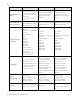
Dell Table 17. Features List for Base Management Functionality, iDRAC, and vFlash Feature Base Management Functionality iDRAC6 Express iDRAC6 Enterprise vFlash Media Interface and Standards Support Web-based GUI SNMP WSMAN SMASH-CLP IPMI 2.
Dell Feature Base Management Functionality iDRAC6 Express iDRAC6 Enterprise vFlash Media Virtual media Virtual console Virtual console sharing Serial-over-LAN Virtual flash Monitoring Real-time Power Monitoring Real-time Power Graphing Historical Power Counters Sensor Monitoring and Alerting Logging Features System Event Log RAC Log Trace Log PowerEdge R610 Technical Guide 55
Dell 17 Peripherals The R610 supports the following USB devices: • • • • DVD (bootable; requires two USB ports) USB key (bootable) Keyboard (only one USB keyboard is supported) Mouse (only one USB mouse is supported) PowerEdge R610 Technical Guide 56
Dell Appendix A. Certifications A.1 Regulatory Certifications Regulatory compliance certificates can be located at the following sites: • http://www.dell.com/content/topics/global.aspx/about_dell/values/regulatory_compliance /dec_conform?c=us&l=en&s=corp A.2 Product Safety Certifications The product has been certified and bears the Mark, as applicable, of the Product Safety authorities as indicated in Table 18. Table 18.
Dell A.3 Electromagnetic Compatibility The product has been certified and bears the Mark, as applicable, of the EMC authorities as indicated in Table 19. Table 19.
Dell A.4 Ergonomics, Acoustics and Hygienics The product has been certified and bears the Mark, as applicable, of the Ergonomics, Acoustics and Hygienics authorities as indicated in Table 20. Table 20.
Dell Appendix B. Additional Information and Options The PowerEdge R610 system conforms to the industry standards detailed in Table 21. Table 21. Industry Standards Standard URL for Information and Specifications ACPI Advance Configuration and Power Interface Specification, v2.0c http://www.acpi.info/ Energy Star EPA Version 1.0 of the Computer Server specification http://www.energystar.gov/index.cfm?c=archives.enterprise _servers Ethernet IEEE 802.3-2005 http://standards.ieee.org/getieee802/802.
Dell Standard URL for Information and Specifications UEFI Unified Extensible Firmware Interface Specification, v2.1 http://www.uefi.org/specs/ USB Universal Serial Bus Specification, Rev. 2.0 http://www.usb.org/developers/docs/ Windows Logo Windows Logo Program System and Device Requirements, v3.10 http://www.microsoft.com/whdc/winlogo/hwrequirements.