Technaxx® * User Manual IP-Cam HD Outdoor with LED Floodlight TX-83 WiFi outdoor camera including LED floodlight lighting Important Hint regarding the User Manuals: All languages of the user manual you find on the CD enclosed. The english and german version of the user manuals you also find as printed version enclosed. Before using the device the first time, read the user manual carefully.
Content Content ................................................................................................................................2 Features...............................................................................................................................3 Technical specifications .......................................................................................................4 1. Device Structure ...............................................................................
The Declaration of Conformity you find here: www.technaxx.de/ (in bar at the bottom “Konformitätserklärung”). Before using the device the first time, read the user manual carefully. Service phone No. for technical support: 01805 012643 (14 cent/minute from German fixed-line and 42 cent/minute from mobile networks). Free Email: support@technaxx.de Hints for Environment Protection: Packages materials are raw materials and can be recycled. Do not disposal old devices or batteries into the domestic waste.
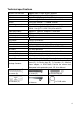
Technical specifications Wireless transmission Light source Detection Lens Shutter Time delay control Minimum illumination Supports 802.11.b/g/n wireless protocol 0.5W / 24x high power LED / Ø 650 Lum Angle 70°~80°, Range 6~10m, PIR 6~8m F = 3.6mm @ F1.2; Horizonal 60.4°; Mount M12 1/50 (1/60) seconds ~ 1/100000 seconds 10 – 120 seconds Colour: 1.0 Lux @ F1.2; AGC ON (0 Lux with IR) B/W: 0.1 Lux @ F1.
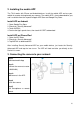
1. Device Structure Front view No. Name 1 White light source 2 3 Fixed hole Microphone 4 Lens 5 PIR sensor 6 Antenna 7 Mounting bracket 8 RJ45 Ethernet connector 9 Reset button 10 11 Power socket MicroSD card slot Side view Description The camera will use these in low-light conditions to generate a black and white image, even in total darkness. The camera can be fixed on a wall with screw through this hole. Allows the camera to pick up nearby sounds, and stream them with the video.
2. Installing the mobile APP The TX-83 works with iPhone and Android devices. Install the mobile APP and use your mobile for remote viewing/control your camera. The mobile APP is free to download for you, and is available from the respective Apple APP Store and Google Play Store. Install APP on Android 1. Open Google Play Store. 2. Search for “Security Advanced”. 3. Touch INSTALL. 4. Review the App’s permissions, then touch ACCEPT to download. Install APP on iPhone/iPad 1. Open the APP Store. 2.
Important Safety Instructions • Make sure product is fixed correctly and stable if fastened in place. • Do not operate if wires and terminals are exposed. • Apply for garden/square/wall/garage etc. Default Password Information • To ensure your privacy, this device supports password protection. • The default, all-access username is admin, the default password is empty. • To ensure your ongoing privacy, we strongly recommend setting a new password as soon as possible.
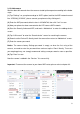
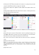
3.1.2 Add camera Wait for about 90 seconds when the camera started up then operate according to the below steps: (1) Tap ”Settings” on your phone and go to “WIFI” option, look for the WIFI network named like “LEDCAM_XXXXXX”, please connect your phone to it by clicking on it. (2) Enter the WIFI password, default value is 0123456789, then click ”Join” to save. (3) Now your phone has been connected to the LED camera WIFI network.
3.2 Method2: Search camera in the LAN 3.2.
(1) Connect the RJ45 Ethernet connection on the camera, to a spare port on your router using the included Ethernet cable (or a longer one if required). (2) Connect the output of the supplied 12V power adapter into the power socket on the camera. (3) Plug the power adapter into the wall socket. Now the camera is initializing and it will last about 90 seconds then enter normal status. 3.2.2 Add camera (1) Start the Security Advanced APP, and Touch the “Add device” to enter the adding device screen.
3.3 Wireless Network Connection If you want to connect the camera to router with WiFi, please enter the camera setting WiFi setting to set up, steps shown in the figure below: (1) Start the Security Advanced APP, Touch the gear shape icon to enter the camera setting screen. (2) Tap “WIFI setting” to enter the WIFI setting screen. (3) Tap “Manage WIFI network” to search the nearby WIFI signals. (4) Select one WIFI SSID which you want to connect to, and tap it. (5) Enter the WIFI router password.
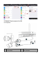
5. Install the WiFi antenna Left and right Up and down Use a clockwise motion to connect the antenna. Make sure the antenna is connected firmly but not excessively. It is recommended to leave the antenna in a vertical position for best reception. 6. Camera installation guide Confused on which location to install your camera? The camera can be installed in a number of different locations. Camera location can depend on the following. 6.
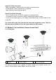
Mount cameras at an elevated position - Mounting your cameras at an elevated position, can keep your cameras out of range of vandals or would be burglars. It also allows your camera to have a high vantage point increasing its viewing area. Cover your target area: When placing cameras, make sure you provide ample coverage, but not in excess. For example, if you are trying to cover a front gate, don’t zoom in to only have the gate in frame.
6.3 Lighting Tips For best results do not point the camera towards a light source. Pointing the camera towards a glass window intending to see outside may result in a poor image because of glare and lighting conditions inside and outside. Do not place the camera in a shaded area that is looking into a well lit area as this will result in a poor display. The light to the sensor located at the front of the camera needs to be the same as the light at the focal target for best results.
Use a screw driver to screw the crossbar into the chosen surface with the included screws (A). Put the included screw (D) through the center hole of the camera bracket and crossbar. Connect the output of the supplied DC12V power adapter into the power socket on the camera. Tighten the screw properly Then plug the power adapter to secure the camera onto into the wall socket. the wall. 6.
7. Main function introduction APP setting 7.1 LED working mode 7.1.1 Turn on /off LED manually (1) Start the Security Advanced APP on the “Device List” screen, touch the gear shaped icon to enter the selected camera setting screen. (2) Tap “Light Setting” to enter the light setting screen. (3) Select “Manual/Auto” to ON. (4) Tap “Done” to save and the LED will be on. (5) Select “Manual/Auto” to OFF. (6) Tap “Done” to save and the LED will be off. 7.1.
(1) Start the Security Advanced APP on the “Device List” screen, tap the gear shaped icon to enter the camera setting screen. (2) Tap “Light Setting” to enter the light setting screen. (3) Tap “Manual Mode Dwell Time” input box. (4) Enter required delay time from 1 to 10 hours. (5) Tap “Done” to save. 7.1.3 Auto mode (1) Start the Security Advanced APP on the “Device List” screen, tap the gear shaped icon to enter the camera setting screen. (2) Tap “Light Setting” to enter the light setting screen.
7.1.4 LED ON Delay time setting at Auto mode (1) Start the Security Advanced APP on the “Device List” screen, tap the gear shaped icon to enter the camera setting screen. (2) Tap “Light Setting” to enter the light setting screen. (3) Tap “Auto Mode Dwell Time” input box. (4) Enter required delay time from 1 to 30 minutes. (5) Tap “Done” to save. 7.
(1) Start the Security Advanced APP on the “Device List” screen, tap the gear shaped icon to enter the camera setting screen. (2) Tap “Light Setting” to enter the light setting screen. (3) Slide the LUX bar between icon and to set up Day/Night switch threshold. You can adjust it according to your needs. (4) Tap “Done” to save. 7.3 PIR trigger sensitivity setting (1) Start the Security Advanced APP on the “Device List” screen, tap the gear shaped icon to enter the camera setting screen.
7.4 Notification push setting for PIR trigger (1) Start the Security Advanced APP on the “Device List” screen, tap the gear shaped icon to enter the camera setting screen. (2) Tap “Alarm Setting” to enter the alarm setting screen.
(3) Enable or disable PIR detection, means enable notification push, means disable notification push. (4) Tap “Done” to save. (5) Tap “About\System setting” to enter system setting screen. (6) Enable all items on this screen. (7) When enable the PIR detection and someone enter the surveillance area, your mobile will pop up a message, then you can slide it to view. 7.
7.6 Recording to a Memory Card You can insert a MicroSD card into MicroSD card slot (Refer to chapter 4 to see how to insert card) for continuous recording. The camera supports MicroSD memory card up to 64GB. (1) Start the Security Advanced APP on the “Device List” screen, tap the gear shaped icon to enter the camera setting screen. (2) Tap “MicroSD card Setting” to enter the MicroSD card setting screen. (3) Here display the MicroSD card total capacity, you can check the MicroSD card inserted or not.
7.7 My messages (1) Start the Security Advanced APP on the “Device List” screen, tap “My messages” to enter my messages screen. (2) Tap a selected camera to enter next screen. (3) Tap to view a picture captured when motion or PIR detection event occurred up. (4) Tap to play back video. 7.
8. WEB Interface 8.1 Wired connection to LAN Tip: If you have already configured the camera, skip the procedure for configuring and continue with the installation of the CD. Power on the IP camera, connect IP camera to router by network cable, meanwhile, connect computer to the same router, example of figure 8-1.
Figure 8-2 It will pop up user login dialog, enter default user name (admin) and password will be empty when the camera is registered for the first time as figure 8-3. Important: After first login change the password! (Chapter 8.8.2 User settings) Figure 8-3 After you logged in you will see options like in figure 8-4 below.
We suggest using Internet Explorer 11 as browser to view the video (it can provide more functions), but user needs to install video player before viewing the video. Click “OCX Download ” to download OCX and install it. You can also find it on CD. Except IE browser, you can visit the camera by Firefox, Safari, Chrome, Opera browser etc., select “videostream mode (for Firefox)” for operating.
Figure 8-6 Notice: When the device is connected both WIFI and wired, it will firstly connect to the wired network. If the camera enables DHCP to obtain IP address automatically, so the IP address is not same in wired connection and WIFI connection. 8.3 View video After installing the plug-in, click “livestream mode (for Internet Explorer),” as Figure 8-4 to view the video. Your display should look similar to figure 8-7.
Audio, Talk, Record, Snapshot You can click snapshot functions. Note: About recording path, click these buttons to perform audio, talk, record and button to enter setting interface. Under Device basic information you can set “Local Recording Path” for saving manual taken snapshots and recordings, as seen in figure 8-8. Figure 8-8 Multipicture change button If you add multiple devices in chapter 8.8.
Horizontal patrol Vertical patrol Reversal Mirror Contrast Brightness Chroma Saturation IR LED switched ON /Auto IR LED Switched OFF Switched OFF Switched ON Resolution: CBR Resolution: VBR PT speed setting: Slow, Medium, Fast Note: button can control work mode of IR LED. IR LED may have auto, forced close two mode, the IR LED will power on or off according to environment light in auto mode; the IR LED always power off in forced close mode.
8.4 Device basic information 8.4.1 Device information The user can obtain “Device firmware version”,” Web UI version”, “Alias”, “MAC” and etc. You also can change the language here. The UPnP setting of the camera is always activated. 8.4.2 Alias setting The user can name the camera, example for home, office etc. 8.4.
8.4.5 MicroSD Card Record Schedule Here you can see the total capacity of the MicroSD card in MB. Also you can format the MicroSD card. Record coverage can be checked to automatically overwrite the oldest file (loop recording). After checking the Timer recording box you can set the time schedule. By clicking on the schedule the activated part turns blue. Every hour is separated into 4 part of 15 minutes. Figure 8-12 8.4.
Device only triggers alarm when it detects any motion in armed time. User can set schedule time to be “all the time”, also assign the armed time. Before you set “Time Schedule”, please go to Date and Time settings to set the correct time Figure 8-13 After enabling Motion Detect Armed you can see the following options. Motion Detect Sensibility Alarm Audio Sensibility Infrared alarm Set the sensibility fro 1 to 10 (The smaller the value, the more sensitivity.
Output Level (not supported) Send Alarm Notification by Mail Set up the output level to low or high Upload picture number (only for FTP server) Alarm recording Scheduler Check the box to get informed by E-mail when motion is detected. The E-mail is with a picture attached. Note: You have to set the E-mail settings first. Check the box. When motion is detected and the FTP server is set the picture will be uploaded to the set FTP server.
8.5.3 FTP Service Setting When alarming, the device will snap local picture and send them to FTP server, but need to set the FTP setting correctly. As figure 8-15, after the setting is finished, click “Test” to check your settings are correct or not. Figure 8-15 Note: For using the FTP function, you need to apply a user with authority that you can write and create submenu and some memory space. For FTP server just insert the IP address. 8.5.4 Log You can inquire when the device performs alarm in alarm log.
8.6 Network configuration 8.6.1 Basic network settings The user can also enter the Basic Network Settings to set the IP address except using the search software “IPCameraSearch”. Default setting here is DHCP. See figure 8-17 below. Figure 8-17 Remark: The router connected to camera need to enable DHCP when the user uses “obtain IP from DHCP server”; the routers enable DHCP by default. 8.6.2 Wireless Lan settings Please refer to chapter 8.2. First scan your environment. Then choose your Wireless network.
8.6.3 DDNS Service setting User can also use DDNS, such as www.dyndns.com, User must apply a free domain name from this website and fill the info into the below blanks (Figure 8-19) and save the settings. Then the domain name can be used. Figure 8-19 Notice: Using the domain name, if the http port is not 80, the port number should be adding to the domain name with colon. Example: http://btest.dyndns.biz:81. Also you have to register a new account for the DDNS service by yourself. 8.
8.8 User and device setting 8.8.1 Multi-device Setting Like Figure 8-21 user can add maximum 9 devices to view video simultaneously. Click “refresh” button to check the device in the LAN. First choose a device on the left, like “The 2nd Device” and click on it. The setting dialogues will popup. Now enter the device info manual (or by clicking on the device you want to be added) fill in user and password. Click “Add” to add device. After that, you must click “Set up” button to save device. Figure 8-21 8.8.
8.8.3 Maintain Figure 8-23 Click “Restore factory settings”, it will pop up a dialog to ask you if restore to factory settings, the camera will restore factory settings and reboot after you confirmed. If there is any issue with the camera you also can reboot the camera by clicking on “Reboot Device”. There are two types of software in the camera, one is the device firmware, another is Web UI and you can upgrade them respectively. 9.
Add camera To add a camera click on “Manage” like seen in figure 9-2. Figure 9-2 In the new window that has opened, click “search” on the bottom, figure 9-3. Figure 9-3 The LAN will be scanned for devices. When a device is found it will be listed, figure 9-4.
Double click on the device name you want to add. See figure 9-5. Enter password and click “OK”, then finish the camera adding. When it is the first time adding the camera and the password wasn’t modified, no need to enter the password, because the factory default value of the password is empty. Figure 9-5 In the main interface of computer software, click the camera in the list and drag it to a channel on the left.
Click next to the camera name (Figure 9-7), and enter the camera setting list you see in figure 9-8. Figure 9-7 Figure 9-8 Note: For your own safety please customize the password before you make any further settings. Go to User setting (figure 9-8) and set a customized user and password. For different user class refer to chapter 8.8.
10. Troubleshooting Q1: I have forgotten the username and password of the camera. A1: The default username is admin and the password is none. If you have changed the username and password to something different, you will need to reset the camera back to its default factory settings. To reset the camera, unplug the power adapter from the power socket then press and hold the Reset button while you reconnect the power adapter to the power socket.
This product includes software developed by third parties, including software which is released under the GNU General Public License Version 2 (GPL v2). This program is free software; you can redistribute it and/or modify it under the terms of the GNU General Public License as published by the Free Software Foundation; either version 2 of the License, or (at your option) any later version.
Also, for each author's protection and ours, we want to make certain that everyone understands that there is no warranty for this free software. If the software is modified by someone else and passed on, we want its recipients to know that what they have is not the original, so that any problems introduced by others will not reflect on the original authors' reputations. Any free program is threatened constantly by software patents.
c) If the modified program normally reads commands interactively when run, you must cause it, when started running for such interactive use in the most ordinary way, to print or display an announcement including an appropriate copyright notice and a notice that there is no warranty (or else, saying that you provide a warranty) and that users may redistribute the program under these conditions, and telling the user how to view a copy of this License.
system on which the executable runs, unless that component itself accompanies the executable. If distribution of executable or object code is made by offering access to copy from a designated place, then offering equivalent access to copy the source code from the same place counts as distribution of the source code, even though third parties are not compelled to copy the source along with the object code. 4.
system; it is up to the author/donor to decide if he or she is willing to distribute software through any other system and a licensee cannot impose that choice. This section is intended to make thoroughly clear what is believed to be a consequence of the rest of this License. 8.
HOW TO APPLY THESE TERMS TO YOUR NEW PROGRAMS (1) If you develop a new program, and you want it to be of the greatest possible use to the public, the best way to achieve this is to make it free software which everyone can redistribute and change under these terms. (2) To do so, attach the following notices to the program.