
Instructions / Assembly
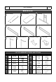
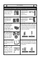
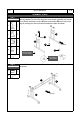
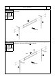
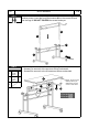
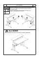
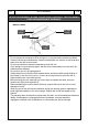
Table Of Contents

ASSEMBLY STEPS
NON-LOCKING
AT THE BACK
LOCKING AT
THE FRONT
G1
(Front)
3
3
G2
F
E
First install the non-locking casters E at the back of the legs 3, and the
locking casters F at the front using the cone wrench (spanner) as shown.
Then attach the plastic covers G1 and screw knobs G2 to the top of the
legs 3, making sure the knob faces towards the back as shown.
STEP 1
Hardware:
E
Non
locking
2
Pcs
F
Locking
2
Pcs
G1
Covers
4
Pcs
G2
Screw
knob
4
Pcs
I
P. 4
RTA-3800SU
P. 4
Assemble the central structure 6 in between the legs 3 using screws A
as shown.
STEP 2
Hardware:
A
M6x38
4
Pcs
H
6
3
3
(Front)