
Instructions / Assembly
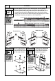
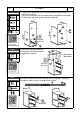


Table Of Contents

Assemble the left panel 16 and the right
panel 18 to the bottom panel 20 with
bolts A as explained in page 4.
STEP 11
Hardware:
A
M6x40
4
Pcs
Scan QR Code
to view this step
((TTop)op)
(F(Froronntt))
((Front))
((TTop)op)
(F(Froronntt))
P. 1 0
RTA-8211
P. 1 0
STEP 12
Hardware:
K
ST5x40
4
Pcs
L
M6x25
2
Pcs
N
1
Pc
Scan QR Code
to view this step
• Assemble the back panel 19 to the bottom panel 20 with bolts L as
explained in page 4.
• Then secure the panel 19 to the side panel 18 with screws K.
• Finally attach the grommet N to the back panel 19.
The back of panel
20 will have 2 free
holes for next step
STEP 13
Hardware:
A
M6x40
4
Pcs
Scan QR Code
to view this step
Assemble the top panel 21 to the
side panels 16 and 18 with bolts A
as explained in page 4.
16
18
Cam lock
alignment
20
N
Cam lock
alignment
L
19
18
16
20
19
18
(F(Froronntt))
((TTop)op)
Cam lock
alignment
This hole is
at the front
16
18
21
K