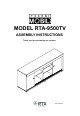
MODEL RTA-9500TV ASSEMBLY INSTRUCTIONS Thank you for purchasing our product. REV.
RTA-9500TV P.1 • Please read carefully the assembly instructions before the installation. • Do not discard this manual or any of the packaging material until the unit has been completely assembled. • Might require two people. P.
RTA-9500TV P.2 P.
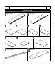
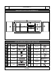
RTA-9500TV P.3 P.3 MAIN PARTS LAYOUT (FOR REFERENCE): 02 10 09 05 03 08 08 07 08 11 04 06 09 11 11 01 LIST OF HARDWARE, SCREWS AND FITTINGS PART QTY ITEM PART QTY ITEM A 32 M8x30 Dowels H 4 Bracket B 22 Bolts I 8 Plastic pin C 22 Cam locks J 22 Covers D 8 ST3.5x14 K 6 Feet E 10 ST4x50 L 4 Sliding tracks F 12 ST3.
RTA-9500TV P.4 P.4 ☛ This unit uses cam bolts and locks. The following explains how to use them. This is not an assembly step; it is a guide for when you are actually doing the assembly using this kind of hardware. Cam Lock Cam Bolt 3. Insert the cam lock on panel “B” making sure it goes aligned to receive the bolt’s head. 4. Turn the cam lock clockwise. This will lock the parts together and will close any gaps. Panel “B” 2. Join panel “B” to panel “A”.
P.5 RTA-9500TV P.5 BEFORE YOU START THE ASSEMBLY, PLEASE READ THE FOLLOWING TIPS AND WARNINGS. ❶ Do a quick inventory to make sure the package contains all the parts and hardware listed in the assembly instructions. ❼ To avoid misalignments, always leave the screws loose and tighten them until all pieces are positioned correctly. ❷ Missing, damaged and defective parts can be replaced at no cost to you. Please refer to the last pages on this manual.
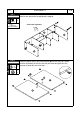
RTA-9500TV P.6 P.6 ASSEMBLY STEPS (Note: the unit will start assembling with its front facing down) STEP 1 Hardware: D ST3.5x14 4 Pcs H 4 Pcs L 4 Pcs • Install brackets H into the groove of panel 10 with screws D. If there are no pre-drilled holes or markings, just calculate a good distance between them, but you must leave at least 1” space from each end. • Install the sliding tracks L on the bottom panel 1 and the Top panel 2.
RTA-9500TV P.7 STEP 3 Install the wooden dowels A into the indicated holes on the profiles of panels 3, 4, 5, 6, 7 and 8. Hardware: A M6x20 P.7 32 Pcs 8 (NOT INCLUDED) 8 7 8 6 4 5 3 Hardware: C Cam lock 8 Pcs • Join the panels 6 and 7 to two of the panels 8, then install the cam locks C and turn them to locks the pieces as explained in page 4. • Note: The panels 8 must have their smooth faces towards the TOP.
RTA-9500TV P.8 Hardware: C Cam lock 4 Pcs • Join the panels 5 and 7 to the third panel 8, then install the cam locks C and turn them to locks the pieces as explained in page 4. • Note: The panel 8 must have its smooth face towards the TOP. (Top) STEP 5 P.8 8 5 (Bottom) (NOT INCLUDED) 7 STEP 6 Hardware: C Cam lock 6 Pcs With the help of another person, join the top panel 2 to panels 5, 6 and 7, then install the cam locks C and turn them to lock the pieces as explained in page 4.
RTA-9500TV P.9 STEP 7 Join panels 3 and 4 to panel 2, then install the cam locks C and turn them to lock the pieces as explained in page 4. Hardware: C Cam lock P.9 4 Pcs Cam locks alignment (NOT INCLUDED) 2 3 06 02 4 STEP 8 Hardware: I 8 Pcs M 2 pcs Install the plastic pins I and the grommets M into the doors 9. Please note the orientation of the pins, as they will enter and glide into the grooves of panel 2 in the next step.
RTA-9500TV P.10 STEP 9 P.10 Join the doors 9 to panel 2 making sure that their plastic pins enter in the grooves, and that each door will go in its own groove. Each door must glide on its own groove. 2 9 9 STEP 10 Hardware: E ST4x50 10 Pcs With the help of another person, assemble the bottom panel 1 to panels 3, 4, 5, 6 and 7 with screws E, but make sure that the plastic pins from the doors enter in the correct and corresponding tracks. Each door should slide on its own track.
RTA-9500TV P.11 STEP 11 Install the feet K to the bottom panel 1 with screws F. Hardware: F ST3.5x25 P.11 12 Pcs 6 Pcs K (NOT INCLUDED) 1 K STEP 12 Hardware: G Nails 24+ Pcs With the help of another person, place the back panels 11 over the unit, calculating that they go as aligned and centered as possible, and secure them with nails G. It is recommended to secure the corners first, then all around.
RTA-9500TV P.12 STEP 13 Hardware: D ST3.5x14 4 Pcs P.12 • With the help of another person, bring the unit upright. • With the help of another person, assemble the top front panel 10 to the top panel 2 by securing the brackets underneath with screws D. (NOT INCLUDED) 2 10 STEP 14 Hardware: J 22 Pcs • You can remove the number stickers from the panels using rubbing alcohol. • Cover the cam locks with J. • If necessary, use the touch-up chalk to cover any light imperfections on the finish.
RTA-9500TV P.13 P.13 CARE, MAINTENANCE AND SAFETY WARNINGS: WEIGHT LIMITS A A = 21 KG - 46.29LB C B C C B = 5 KG - 11.02LB B C = 4 KG - 8.81LB • Do not exceed the indicated weight limits. • Do not expose the surfaces to direct sunlight or to extreme environmental conditions. • Clean the surfaces preferable with a clean cloth damped in a solution of mild soap and water, then dry with a clean towel. • Do not use solvents or abrasive materials to clean the unit.
P.14 RTA-9500TV P.14 TECHNI MOBILI WARRANTY DESKS/LAPTOP CARTS/FILE CABINETS: LIMITED 5-YEAR WARRANTY TV Stand/Entertainment Center: 2 YEAR WARRANTY RTA Products, LLC warrants to the Original Purchaser who acquired a new product from RTA Products or its authorized resellers that this product will be free from defects in its workmanship and materials, under normal use and service conditions, as described herein.
P.15 RTA-9500TV P.15 FOR SEVERAL HELP OPTIONS INCLUDING REPLACEMENT PARTS ORDERS _________________________________________________________________ VISIT: WWW.TECHNIMOBILI.COM CLICK ON SUPPORT TAB Scan QR Code to order replacement parts OR EMAIL US: SUPPORT@RTAPRODUCTS.