MODEL RTA-TS201 ASSEMBLY INSTRUCTIONS Thank you for purchasing our product. REV.
RTA-TS201 P.1 • Please read carefully the assembly instructions before the installation. • Do not discard this manual or any of the packaging material until the unit has been completely assembled. • Might require two people. P.
RTA-TS201 P.2 P.
RTA-TS201 P.3 P.
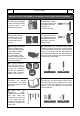
P.4 RTA-TS201 P.4 BEFORE YOU START THE ASSEMBLY, PLEASE READ THE FOLLOWING TIPS AND WARNINGS. ❶ Do a quick inventory to make sure the package contains all the parts and hardware listed in the assembly instructions. ❼ To avoid misalignments, always leave the screws loose and tighten them until all pieces are positioned correctly. ❷ Missing, damaged and defective parts can be replaced at no cost to you. Please refer to the last pages on this manual.
RTA-TS201 P.5 P.5 ASSEMBLY STEPS STEP 1 Hardware/tools: Insert the studs 16 to the bottom of the leg structures left 1 and right 2 as shown. 4 Pcs 16 1 16 2 16 STEP 2 Hardware/tools: A G M6x12 Ø10mm Assemble the top structure 3 between the legs 1 and 2 with screws A and O-Rings G from inside as shown.
RTA-TS201 P.6 STEP 3 Hardware/tools: B M6x15 P.6 Using screws B, assemble the back structure 4 to the leg structures left 1 and right 2 as shown. 4 Pcs 4 1 2 STEP 4 Hardware/tools: C M6x25 4 Pcs Using screws C, assemble the LEFT “L” structure 8 to the LEFT structure 1, and the RIGHT “L” structure 9 to the RIGHT structure 2 as shown. 10MM VERY IMPORTANT: Pay attention to the correct position of the parts. If switched, the tubes 5 and 6 won’t fit when doing step 6.
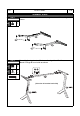
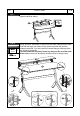
RTA-TS201 P.7 STEP 5 Hardware/tools: D E M6x35 M6x40 1 Pc 1 Pc P.7 With the parts oriented as shown, first insert the screw E in the center hole of the top support tube 5. Then insert the connector tube 7 to the screw E. Finally, insert one screw D through the center hole of the bottom support tube 6 and screw it into the tube 7 as shown. DO NOT TIGHTEN THE SCREW YET TO ALLOW FLEXIBILITY FOR THE NEXT STEP.
RTA-TS201 P.8 STEP 7 Hardware/tools: A C D M6x12 M6x25 M6x35 2 Pcs 2 Pcs 1 Pc P.8 Pay attention to the correct screws that will need to be used. To avoid misalignments, first place all the screws loosely. Working with the frame facing towards the front, and with the help of another person, place the main panel 12 over it making the holes coincide. Then screw loosely using the following screws: A: For the front holes. C: For the back holes. D: For the center hole.
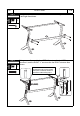
RTA-TS201 P.9 P.9 Place the monitor shelves making sure the hooks secure on the top support tube 5 as shown. STEP 9 11 11 10 5 STEP 10 Hardware/tools: F ST4x14 9 Pcs Using screws F, assemble on either side and from underneath the main panel 12, the large cup holder 13, the small cup holder 15, and the headset hanger 14. You can install the headset hanger 14 facing either way inward or outwards.
P.10 RTA-TS201 ALL DONE! Give yourself a nice pat on the back. You did a great job! P.
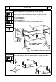
RTA-TS201 P.11 P.11 AFTER THE ASSEMBLY IS DONE, PLEASE READ CAREFULLY THE FOLLOWING CARE AND MAINTENANCE WARNINGS: WEIGHT LIMITS 11 Lbs. (5 Kg) 110 Lbs. 3.25 Lbs. (1.5 Kg) (50 Kg) 3.25 Lbs. (1.5 Kg) • Do not exceed the indicated weight limits. • Do not expose the surfaces to direct sunlight or to extreme environmental conditions. • Clean the surfaces preferable with a clean cloth damped in a solution of mild soap and water, then dry with a clean towel.
P.12 RTA- P.12 TECHNI SPORT WARRANTY Gaming Chair: 2-YEAR WARRANTY Gaming Desk: 5-YEAR WARRANTY Gaming Chair Metal Frame: LIFETIME WARRANTY RTA Products, LLC has warranted the Techni Sport products to the original purchaser who acquired a new product from RTA Products or its authorized re-sellers of the product against defects in material or workmanship.
P.13 RTA-TS201 P.13 FOR SEVERAL HELP OPTIONS INCLUDING REPLACEMENT PARTS ORDERS _________________________________________________________________ VISIT: WWW.TECHNISPORTUSA.COM CLICK ON SUPPORT TAB Scan QR Code to order replacement parts OR EMAIL US: SUPPORT@TECHNISPORTUSA.