Table of Contents Chapter 1: Product Overview ........................................................................................ 6 1.1 Features ................................................................................................................. 6 1.2 Package Contents.................................................................................................. 7 1.3 Hardware Overview .............................................................................................. 8 1.3.
5.3.2 DHCP Setting ...................................................................................... 36 5.3.3 DHCP Reserved Address ..................................................................... 38 5.4 Time and Date ..................................................................................................... 39 Chapter 6: Advanced ................................................................................................... 41 6.1 6.1 Advanced Wireless ............................
6.9.4 DOS Protection ................................................................................... 64 6.9.5 Domain Blocking ................................................................................ 65 6.9.6 DMZ..................................................................................................... 65 6.9.7 SPI Settings ......................................................................................... 66 6.10 Packet Filter .....................................................
Chapter 8: Status.......................................................................................................... 95 8.1 Summary.............................................................................................................. 95 8.2 IPv6 Info............................................................................................................... 95 8.3 ADSL Info............................................................................................................. 96 8.
Product Overview Chapter 1: Product Overview Thank you for choosing Technicolor® Wireless ADSL2+ Gateway. This Wireless Gateway combines the functionality of an ADSL modem and Internet gateway in one. You can access the Internet and share resources such as printers, scanners, and files, via a wireless connection or through one of the Ethernet ports. The various security features, such as WPS, WPA2, SPI, and NAT, protect your data and privacy online.
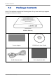
Product Overview 1.2 Package Contents Check if the package contains the following items. If any item is missing or appears damaged, contact your dealer.
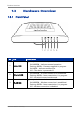
Product Overview 1.3 1.3.1 Hardware Overview Front Panel 1 2 3 4 5 6 No. LED Description Lights up when the device is powered on. 1 Power LED 2 Ethernet LED • • • • Solid GREEN – Indicates normal operation. Flashing GREEN – Firmware upgrade in progress. Solid RED – Indicates malfunction. Off – The device is powered off. • • • Solid GREEN – A wired connection is established. Flashing GREEN – Data transmission is in progress. Off – No wired connection detected.
Product Overview No. LED Description Lights up to indicate the Wi-Fi Protected Setup (WPS) connection status. 4 WPS LED • • • • Solid GREEN – WPS-enabled device is connected. Flashing GREEN – Data transmission is in progress. Flashing RED – WPS connection failed. Off – WPS is disabled. Lights up to indicate DSL connection status. 5 Broadband (DSL) • LED • • Flashing GREEN – Attempts to synchronize with DSL line. Solid GREEN – DSL connection is established. Off – DSL connection is not present.
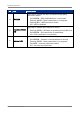
Product Overview 1.3.2 Rear Panel 1 No. 23 4 5 6 7 8 Ports / Buttons Description 1 DSL port Connects to the DSL line using the RJ-11 cable. 2 Reset button Press and hold this button for at least 10 seconds to restore your device to its original factory default setting. 3 LAN LED 1, 2 The LAN LED (1, 2) lights up when a device is connected to the Ethernet port (1, 2).
Installation Chapter 2: Installation Make sure that all devices are powered off before starting installation. Installation Diagram 2.1 Connect the Power 1. Connect the power adapter to the DC In jack of your Wireless Gateway. 2. Plug the power adapter to a wall outlet or a power strip. NOTE: • • Use only the supplied power adapter. Using other power adapters may cause damage to the device. Connect all devices to your Wireless Gateway before connecting the power adapter to a wall outlet.
Installation 2.2 Connect Wired Devices Connect devices such as computers, printers, and other Ethernet-enabled devices to the LAN port of the Wireless Gateway. NOTE: When setting up the Wireless Gateway for the first time, connect the host computer via Ethernet connection. 1. Connect one end of the RJ-45 cable to one of the Ethernet (1, 2, 3, 4) ports of your Wireless Gateway. 2. Connect the other end of the RJ-45 cable to the Ethernet port of the computer. 3.
Installation 2.4 Connect the Broadband (DSL) 1. Connect one end of the RJ-11 cable to the DSL port of your Wireless Gateway. 2. Connect the other end of the RJ-11 cable to a wall jack with DSL service. 2.4.1 Use a Splitter You need a splitter when connecting the Wireless Gateway to the wall jack that also connects to a telephone. 1. Plug the splitter to the wall jack with DSL service. 2. Connect one end of the RJ-11 cable to the DSL port of your Wireless Gateway. 3.
Configure the Computer Chapter 3: Configure the Computer This chapter will guide you on how to configure your computer according to the operating system you are using. Windows® XP, see below. Windows® Vista, see page 16. Windows® 7, see page 16. 3.1 Windows XP If you are using Windows® XP, follow the instructions below to configure your computer. 1. Click Start > Control Panel > Network Connections. 2. Right-click Local Area Connection, then click Properties. 3.
Configure the Computer 3.2 Windows Vista If you are using Windows® Vista, follow the instructions below to configure your computer. 1. Click Start > Control Panel > Network and Internet Connections > Network Connections. 2. Right-click Local Area Connection, then click Properties. 3. On the General tab, make sure that Internet Protocol (TCP/IP) is checked. If not, check it to enable the Properties button. 4. Select Internet Protocol (TCP/IP), and then click Properties. 5.
Log In to the Modem Router Chapter 4: Access the Wireless Gateway Use the Web Configurations utility to configure your Wireless Gateway. 1. Launch the web browser. 2. On the address bar, enter http://192.168.1.1, then press Enter. NOTE: • For first time access, the Setup Wizard appears. See below. • If the Web Configurations utility has been left idle for some minutes, the system may prompt you to login; enter the User name and Password. The default user name is “root” and the password is empty.
Log In to the Modem Router 2. Select a network protocol. Click Next to continue. The information required on the succeeding pages varies depending on the network protocol you select here. 3. Select a scanning method, and then click Next to continue. • • Auto Scan: The Wireless Gateway automatically scans for Virtual Path Identifier (VPI) and Virtual Channel Identifier (VCI). Manual Scan: To allow you to configure the VPI and VCI manually. 4. If Auto Scan is selected, skip to step 5.
Log In to the Modem Router a. b. c. d. e. f. g. Enter desired Profile Name. Enter the Virtual Path Identifier (VPI) and Virtual Channel Identifier (VCI). Select an Encapsulation mode: LLC, VCMUX. Select the ATMQoS option. Enter a Peak Cell Rate. Enable or disable Default VLAN and PPPoE PassThrough. Click Next to continue. 5. The displayed screen varies depending on the network protocol you selected on step 2. Obtain the required information from your ISP. The following is a PPPoE example. a. b. c. d.
Log In to the Modem Router 6. Select whether to enable or disable wireless connection. From this point, you can also change the SSID with a name that you can easily remember. Click Next to continue. 7. Select the Security Mode, Authentication Type, and Encryption, and enter a passphrase. Click Next to continue. The screen below varies depending on the security mode you selected, below is an example of a WPA security screen. 8. When prompted to reboot, click OK.
Log In to the Modem Router 9. To reboot the Wireless Gateway, click Reboot. 4.2 Menu Use the main menu, located on the left panel of the screen, to manually configure your Wireless Gateway. Click a menu item, then a submenu to display the page on the screen. For submenus with more options, move the mouse cursor over the submenu to view the options.
Setup Chapter 5: Setup The Setup menu allows you to configure the Internet connection of your Wireless Gateway manually. 5.1 Internet Setup The Internet Setup page is divided into three sections: Internet Connection Settings, Internet Settings, and Protocol. To access the Internet Setup page, click SETUP > Internet Setup. 5.1.1 Internet Connection Settings This setting configures the Wireless Gateway to your Internet connection. The required settings should be obtained from your ISP.
Setup Enable Default Vlan — Select whether to enable or disable VLAN tagging. PPPoE PassThrough — Select whether to enable or disable PPPoE passthrough. 5.1.2 Internet Settings DSL lines use different network protocols to establish Internet connection.
Setup State of Connection — Select whether to enable or disable this connection. IP Protocol Version — Select the type of IP protocol to use with this connection: • • • IPv4 only: Select to use IPv4 protocol. IPv4/v6 both: Select to use this connection in both IPv4 and IPv6 protocols. IPv6 only: Select to use IPv6 protocol. IPMode of Connection — Select the connection mode, options are: • • Dynamic: Select Dynamic if the IP address can be automatically obtained from your ISP.
Setup LCP Interval — Enter the number of seconds that you want to be the interval in sending LCP (Link Control Protocol) packets. As system default route — Check this box to set the current setting as the default route. ICMP Reply Enable — Check this box to enable ICMP (Internet Control Message Protocol) messages to be sent back to the host that sent the message. Proxy ARP Enable — Check this box to enable proxy ARP function.
Setup IPMode of Connection — Select the connection mode, options are: • • Dynamic: Select Dynamic if the IP address can be automatically obtained from your ISP. Static: Select Static if you are required to use a permanent IP address to connect to the Internet. You must enter the IP Address and Subnet Mask provided by your ISP. Name — Enter your desired connection name. NAT — Select whether to enable or disable NAT (Network Address Translation).
Setup NOTE: If the IPv6 protocol is selected, the web utility may prompt for you to configure the IPv6 connection settings. See “IPv6 WAN” on page 48. IPoA (RFC-1483 Routed) If you select IPoA (IP over ATM), the screen below is displayed. State of Connection — Select whether to enable or disable this connection. IP Protocol Version — Select the type of IP protocol to use with this connection: • • • IPv4 only: Select to use IPv4 protocol.
Setup ICMP Reply Enable — Check this box to enable ICMP (Internet Control Message Protocol) messages to be sent back to the host that sent the message. Proxy ARP Enable — Check this box to enable proxy ARP function. Click the Apply button to save your changes or click the Cancel button to discard your changes. NOTE: If the IPv6 protocol is selected, the web utility may prompt for you to configure the IPv6 connection settings. See “IPv6 WAN” on page 48.
Setup DNS Server 1 and DNS Server 2 — If provided by your ISP, enter the DNS server. Otherwise, leave these fields blank. MAC Address — Displays the cloned MAC address. Click the Clone Mac button to clone the MAC address of your computer. Option 125 — Select whether to enable or disable Option 125. Option 60 Vendor ID — Enter option 60 vendor ID. Option 61 IAID — Enter option 61 IAID. Option 61 DUID — Enter option 61 DUID.
Setup • • IPv4/v6 both: Select to use this connection in both IPv4 and IPv6 protocols. IPv6 only: Select to use IPv6 protocol. Name — Enter your desired connection name. NAT — Select whether to enable or disable NAT (Network Address Translation). Enable this setting to share one WAN IP address with multiple computers on your network. External IP Address — Enter the IP address provided by your ISP. Subnet Mask — Enter the subnet mask provided by your ISP.
Setup Name — Enter your desired connection name. Click the Apply button to save your changes or click the Cancel button to discard your changes. NOTE: If the IPv6 protocol is selected, the web utility may prompt for you to configure the IPv6 connection settings. See “IPv6 WAN” on page 48. CIP (RFC-1577) If you select CIP (RFC-1577 Classic RP/ARP over ATM), the screen below is displayed. State of Connection — Select whether to enable or disable this connection.
Setup DNS Server 1 and DNS Server 2 — If provided by your ISP, enter the DNS server. Otherwise, leave these fields blank. As system default route — Check this box to set the current setting as the default route. ICMP Reply Enable — Check this box to enable ICMP (Internet Control Message Protocol) messages to be sent back to the host that sent the message. Proxy ARP Enable — Check this box to enable proxy ARP function.
Setup Wireless Channel — Select the appropriate channel that corresponds to your network settings. You should assign different channels for each access point to avoid signal interference. TIP: Select Auto for Wireless Channel to allow your Wireless Gateway to select the best possible channel for your wireless network. Wireless Mode — Select the wireless mode to limit the type of wireless devices that can connect to the network. Options are: • • • • • 5.2.2 802.11b only: Only 802.
Setup Security Mode — Select the security and the encryption type to use. Select None if you do not want to use any security mode. WEP WEP (Wired Equivalent Privacy) is the basic security method. With WEP security, all wireless devices must enter the same key to connect to the network. Authentication Type — Select an authentication type. Options are: • • • Auto: Select Auto if you are unsure which authentication is suitable for your wireless devices.
Setup WPA / WPA2 Select WPA (Wi-Fi Protected Access) or WPA2 for better encryption. Authentication Type — Select an authentication type. Options are: • PSK: Select to use a passphrase for authentication. If you select PSK, enter a passphrase in the Confirmed Passphrase field. • EAP — Select to use Extensible Authentication Protocol (EAP). This should only be used when a Radius server is connected to your Wireless Gateway.
Setup WPA/WPA2+TKIP/AES Select this security mode if you are unsure which mode is suitable for your wireless devices. Authentication Type — Select an authentication type. Options are: • PSK: Select to use a passphrase for authentication. If you select PSK, enter a passphrase in the Confirmed Passphrase field. • EAP: Select to use Extensible Authentication Protocol (EAP). This should only be used when a Radius server is connected to your Wireless Gateway.
Setup 5.3 Local Network To access the Local Network page, click SETUP > Local Network. 5.3.1 LAN This section contains the local settings of your network. These settings are private to your internal network and cannot be seen on the Internet. It is recommended to keep the default values. IP Address — The default value is 192.168.1.1. Subnet Mask — The default value is 255.255.255.0. Local Domain Name — Enter a name to refer to the group of devices that will be assigned addresses from this pool.
Setup The information required on the DHCP Setting screen vary depending on the selected DHCP option. DHCP Option — Select the DHCP mode of your Wireless Gateway. Options are: • • • Disabled: Select this setting if there is already a DHCP server on your network and all devices on your network use static IP addresses. DHCP Server: By default, your Wireless Gateway is set as a DHCP server. See more details below. DHCP Relay: Select this setting to set your Wireless Gateway as a DHCP Relay agent.
Setup • Primary DNS Server and Secondary DNS Server — Enter a primary and a secondary DNS server of the sub range. Extra Option Enable — Check this box to enable extra options. • Option 240, Option 241, Option 242, Option 243, Option 244, and Option 245: Enter a name for the corresponding option. Click the Apply button to save your changes or click the Cancel button to discard your changes. DHCP Relay Some ISPs function as the DHCP server for their clients’ small office network.
Setup Enable — Check this box to enable this function. IP Address — Enter the IP address to reserve. MAC Address — Enter the MAC address of the device to reserve the IP address to. Click the Apply button to save your changes; the reserved IP address is listed on the DHCP Reserved Address table. Or, to discard changes, click the Cancel button. 5.
Setup Sync By Time Zone Time Zone — Select the time zone in your location. To set the network time and date according to the selected time zone, click the Sync Time button at the bottom of the screen. Sync With NTP Server NTP (Network Time Protocol) — Check the Enable box to synchronize the network time and date with an NTP server. • • • • Server 1 IP or Domain name: Enter the IP address or the domain name of the NTP server to synchronize your network with.
Advanced Chapter 6: Advanced The Advanced menu configurations greatly affect the operating performance of your Wireless Gateway. This menu is intended for advance users. It is recommended to retain the default settings if you are unsure about them. 6.1 6.1.1 6.1 Advanced Wireless Wireless Router Settings This page allows you to configure advanced wireless router settings. Click Advanced > Advanced Wireless > Advanced Wireless or click the Advanced Setting button.
Advanced WMM (Wi-Fi Multimedia) — Select whether to enable or disable WMM. The WMM feature enhances the Quality of Service (QoS) of a network that is used by multimedia applications such as Voice-over-IP (VoIP) and video. If WMM is enabled, multimedia applications on your network have priority over regular data packets, allowing multimedia applications to run smoother and with fewer errors.
Advanced 6.1.2 MBSSID Settings This page allows you to configure up to four virtual access points (VAP). Click Advanced > Advanced Wireless > MBSSID Setting or click the MBSSID Setting button. Check the corresponding Enabled box of the VAP to enable it. If you enable a VAP, you can modify its SSID and check its SSID Advertise box to allow wireless devices scanning for a wireless network to detect the VAP. Click the Apply button to save your changes or click the Cancel button to discard your changes. 6.
Advanced To Set MAC Filter Do the following to deny or allow a device to access to the wireless network. 1. On the MAC Address field, enter the MAC address of the device that you want to deny or allow access. 2. Click the Add button to add the MAC address to the MAC ADDRESS LIST. 3. Select the MAC Restrict Mode. Options are: • • • Disable: No restriction or disable a previously set restriction. Deny: To deny device to access to the wireless network.
Advanced Enable WPS — Check this box to prompt WPS-enabled devices to enter the PIN before allowing access to the wireless network. Device Password (PIN) — Displays the PIN password. To generate a new PIN, click the Generate New PIN button. To reset the PIN to default, click the Reset PIN to Default button. This PIN must be entered by wireless devices to connect to the wireless network. To reset the WPS setting to not configured, click the Reset to Not-configured button.
Advanced 6.2.2 IP/PPP Config This page allows you to create multiple Wide Are Networks (WAN) and manually add an IP or a PPP connection. To access the IP/PPP Config page, click Advanced > Multi-WAN > IP/PPP Config or click the WAN Config button. To add an IP or PPP connection, do the following: 1. Click the Add button of the corresponding connection that you want to add. The connection screen appears; required settings vary depending on the type of connection that you want to add. 2.
Advanced Change Default Route — Select the connection to set as the default route from the drop-down list. Click the Apply button to save your changes or click the Cancel button to discard your changes. 6.3 Advanced-LAN This page allows you to add multiple LAN IP addresses of the Wireless Gateway. To access the Advanced-LAN page, click Advanced > Advanced-LAN. Spanning Tree Enable — Check this box to enable spanning tree. LLMNR — Check this box to enable Link Local Multicast Name Resolution (LLMNR).
Advanced 6.4 IPv6 WAN This page allows you to configure IPv6 settings. To access the IPv6 WAN page, click Advanced > IPv6 WAN. The table lists the existing IPv6 connection settings. To edit an entry, click the corresponding icon. To delete an entry, click the corresponding button. To add a new connection, click the Add button. All required information must be obtained from your Internet Service Provider (ISP). 6.4.1 Static IPv6 On My IPv6 Connection is, select Static IPv6.
Advanced DS-Lite — Check this box to enable the Dual-Stack Lite (DS-Lite) function. DS-Lite is used to omit IPv4 address deployment from Customer-premises equipment (CPE) devices but instead use the global IPv6 address provided. AFTR IPv6 Address — Enter an After Family Transition Router (AFTR) IPv6 address. Click the Apply button to save your changes or click the Cancel button to discard your changes. 6.4.
Advanced DS-Lite — Check this box to enable the Dual-Stack Lite (DS-Lite) function. DS-Lite is used to omit IPv4 address deployment from Customer-premises equipment (CPE) devices but instead use the global IPv6 address provided. AFTR IPv6 Address — Enter an After Family Transition Router (AFTR) IPv6 address. Click the Apply button to save your changes or click the Cancel button to discard your changes. 6.4.3 PPPoE On My IPv6 Connection is, select PPPoE.
Advanced DS-Lite — Check this box to enable the Dual-Stack Lite (DS-Lite) function. DS-Lite is used to omit IPv4 address deployment from Customer-premises equipment (CPE) devices but instead use the global IPv6 address provided. AFTR IPv6 Address — Enter an After Family Transition Router (AFTR) IPv6 address. Click the Apply button to save your changes or click the Cancel button to discard your changes. 6.4.4 IPv6 in IPv4 Tunnel On My IPv6 Connection is, select IPv6 in IPv4 Tunnel.
Advanced 6.4.5 6 to 4 On My IPv6 Connection is, select 6 to 4. Connection Name — Select an Internet connection to use. This is the connection that you set up in SETUP > Internet Setup page. See “Internet Setup” on page 21. 6 To 4 Settings Connection Name — Enter the connection name provided by your ISP or a desired connection name. 6to4 IPv4 Address — Enter the 6 to 4 IPv4 address provided by your ISP. 6to4 IPv6 Address — Enter the 6 to 4 IPv6 address provided by your ISP.
Advanced 6.4.6 6rd On My IPv6 Connection is, select 6rd. Connection Name — Select an Internet connection to use. This is the connection that you set up in SETUP > Internet Setup page. See “Internet Setup” on page 21. 6rd Settings Connection Name — Enter the connection name provided by your ISP or a desired connection name. 6rd IPv6 Prefix — Enter the 6rd address and prefix provided by your ISP. IPv4 Address — Enter the IPv4 address and Mask Length provided by your ISP.
Advanced 6.5 IPv6 LAN After creating IPv6 WAN, create IPv6 LAN to configure local IPv6 addresses. To access the IPv6 WAN page, click Advanced > IPv6 LAN. WAN Interface — Select the IPv6 WAN interface. This is the IPv6 interface that you created in ADVANCED > IPv6 WAN page. See “IPv6 WAN” on page 48. LAN Link-Local Address — Displays the Wireless Gateway LAN Link-Local address. 6.5.1 IPv6 LAN Stateless After selecting the WAN interface, on Autoconfig Type, select stateless. More fields appear.
Advanced Advertise Local Address Prefix — Check this box to advertise the local address prefix. LAN Local Address — Enter the Wireless Gateway LAN local address. IPv6 Local Address Prefix — Enter the IPv6 local address prefix. Available only if Advertise Local Address Prefix is enabled. IPv6 Global Address Prefix — Enter the IPv6 global address prefix. Lifetime — Enter the advertisement lifetime (in minutes). Click the Apply button to save your changes or click the Cancel button to discard your changes. 6.
Advanced IPv6 Address Range (max) — Enter the ending range of IPv6 address for your local computers. Lifetime — Enter the advertisement lifetime (in minutes). Click the Apply button to save your changes or click the Cancel button to discard your changes. 6.6 ADSL Settings This page allows you to select ADSL modulations, capabilities, and other options. Consult your ISP to determine the appropriate settings. To access the ADSL Settings page, click Advanced > ADSL Settings.
Advanced To add RIP settings, do the following: 1. Select the Interface. 2. On the Receive Mode and Send Mode drop-down lists, select the appropriate versions. NOTE: The selected versions should match the versions supported by the other routers on your network. 3. Click the Add button. To delete an RIP setting, click the corresponding 6.8 6.8.1 button.
Advanced Rule Name — Enter a rule name or select an application name from the drop-down list on the right, then click the << button. If you select a predefined application name, the Public Port, Private Port, and Protocol Type are automatically configured. DSL Interface — Select a DSL interface from the drop-down list. Public Port — Enter the public port. This is the port seen from the WAN side. Private Port — Enter the private port. This is the port being used by applications within your local network.
Advanced Use Interface — Select a DSL interface from the drop-down list. Trigger Port — Enter the port that will trigger the device to open ports for incoming data. Trigger Port Protocol — Select the trigger port protocol from the drop-down list. Public Port — Enter the public port to be opened. Public Port Protocol — Select the public port protocol. Time Schedule — Select a schedule to apply port triggering from the drop-down list or click the New Time Schedule button to create a new schedule.
Advanced IRC — Internet Relay Chat (IRC) is a real-time Internet chatting protocol designed for group communications. Check this box to enable this function to work through your Wireless Gateway. H323 — H.323 is a standard that provides audio-visual communication sessions on a network. It is widely implemented in voice and video conferencing equipments and is used within various Internet real-time applications such as NetMeeting. Check this box to enable this function to work through your Wireless Gateway.
Advanced 6.9 6.9.1 Firewall MAC Filter This page allows you to set up a list of MAC addresses which will be allowed or restricted to access the Internet. To access the MAC Filter page, click ADVANCED > Firewall > MAC Filter or click the MAC Filter button. MAC Address Control — Check this box to enable the MAC filter function.
Advanced The table lists the existing filter rules. To edit an entry, click the corresponding icon. To delete an entry, click the corresponding button. To add a filter, click the Add button. The IP Filter Config screen is displayed. IP Filter — Check this box to enable IP filtering. Filter Name — Enter a filter rule name. Start Source IP Address — Enter the starting point of the source IP address. End Source IP Address — Enter the ending point of the source IP address.
Advanced 6.9.3 URL Filter This page allows you to deny network devices to access specific URLs or URLs that contain specific keywords. To access the URL Filter page, click ADVANCED > Firewall > URL Filter or click the URL Filter button. URL Filter — Check this box to enable URL filtering. Show Redirect Page — Check this box to redirect devices to another website when the website they are trying to access is blocked.
Advanced 2. Select the time to implement the URL filter or click the New Time Schedule button to create a new schedule. 3. Click the Add button of the Add Keyword Rule. The entry is listed on the URL LIST table. To delete an entry, click the corresponding 6.9.4 button. DOS Protection This page allows you to protect your network from hackers to run Denial of Service (DoS) attacks. To access the DOS Protection page, click ADVANCED > Firewall > DOS Protection or click the DOS Protection button.
Advanced Dos Protection Option — Check the appropriate boxes to enable protection from SYN flood, FIN flood, UDP flood, ICMP flood, SMURF, IP spoofing, and others. Enter the flood count numbers or retain the default values if you are unsure about them. Check the Apply button to save and activate DoS protection or click the Cancel button to discard your changes. 6.9.5 Domain Blocking This page allows you to deny network devices to access specific domains such as an http and an ftp.
Advanced DMZ — Check this box to enable DMZ. DSL Interface — Select the DSL interface to activate DMZ from the drop-down list. DMZ Host IP Address — Enter the IP address of the computer to set as the DMZ host. Check the Apply button to save and activate DMZ. 6.9.7 SPI Settings SPI (Stateful Packet Inspection) filters more kinds of attacks by closely examining packet data structures. To access the SPI Settings page, click ADVANCED > Firewall > SPI Settings or click the SPI Settings button.
Advanced 6.10 Packet Filter 6.10.1 Filters & Rules This page allows you to create packet filters and rules. These filters are used to check each data that passes within your network. If the packet data does not meet the requirements, the packet is either dropped or rejected. To access the Filters & Rules page, click ADVANCED > Packet Filter > Filters & Rules or click the Filters & Rules button. Filters Click the Add button to create a new filter. Name — Enter desired filter name.
Advanced Filter Name — Select the filter to assign the rule. Enable — Check this box to enable this rule. Ether Type — Select the Ether type: IP (0x800) or IPv6 (0x86DD). Protocol — Select a protocol from the drop-down list. Options are TCP, UDP, or ICMP. Action — Select the action to execute when the rule requirement is met. Options are: • • • Drop: Select to drop the packets if the rule requirement is met. Permit: Select to allow packets to pass through if the rule requirement is met.
Advanced 6.10.2 Statistics This page displays the filter and rule statistics. To access the Statistics page, click ADVANCED > Packet Filter > Statistics or click the Statistics button. Click the Refresh button to refresh the list. 6.11 Static Route This page allows you to create routing tables for IPv4 and IPv6 protocols. To access the Static Route page, click ADVANCED > Static Route. To create a static route, click the Add button under the desired IP protocol static route table.
Advanced IPv6 Static Route Rule Enable — Enable or disable rule. Forwarding Policy Option — Select whether to enable or disable routing. Rule Name — Enter desired rule name. Source IP — Enter the source IP address. Dest IP — Enter the destination IP address. Gateway — Enter the gateway. Interface name — Select the interface to implement the routing. Click the Apply button to save and activate the static route or click the button to discard your changes. 6.
Advanced To access the Multicast IGMP page, click ADVANCED > Multicast > IGMP or click the IGMP button. IGMP Proxy IGMP proxy enables your Wireless Gateway to forward multicasts traffics between LAN and WAN networks. 1. On IGMP Option, select Proxy. 2. Click the Apply button. 3. Click the Apply button again. More fields appear on the screen. 4. Select the IGMP Proxy Version.
Advanced 5. Select the DSL Interface to implement IGMP. Connected interfaces are displayed in the Connected Interfaces fields. 6. To enable IGMP fast leave option, check the IGMP Fast Leave box. 7. Enter values for IGMP Query Interval, Robust Count, IGMP Last Member Query Interval, IGMP Robustness, Query Response Interval, and Group Live Delay Time. If you are unsure about them, leave the default values. 8.
Advanced 6. Enter values for IGMP Last Member Query Interval, IGMP Last Member Query Count, Query Response Time, Host Timeout, Leave Timeout, or IGMP Max Groups. If you are unsure about them, leave the default values. 7. Check the Enable IGMP box for WLAN, LAN1, LAN2, LAN3, or LAN4 to enable IGMP in the respective network connection. 8. Click the Apply button to save and apply changes. 6.12.2 MLD Multicast Listener Discovery (MLD) is a component of IPv6.
Advanced 4. Enter values for Query Interval, Robust Count, Last Member Query Interval, Last Member Query Count, and Query Response Interval. If you are unsure about them, leave the default values. 5. Click the Apply button to save and apply changes. MLD Snooping With MLD snooping, your Wireless Gateway can make intelligent multicast forwarding to connections that have group members attached in IPv6 protocol. 1. On MLD Option, select Snooping. 2. To enable fast leave option, check the Fast Leave box. 3.
Advanced 6.13 Dynamic DNS Each time your Wireless Gateway connects to the Internet, your ISP assigns a different IP address to your device. In order to access your device from the WAN side, you need to manually track the IP that is currently used. The Dynamic DNS (DDNS) feature allows you to register your device with a DNS server and use the same host name to access your device. To access the Dynamic DNS page, click ADVANCED > Dynamic DNS. The table lists the current DDNS.
Advanced 6.14 Ethernet Setting This page allows you to set the link mode and enable flow control for each of the four LAN ports of your Wireless Gateway. To access the Ethernet Setting page, click ADVANCED > Ethernet Setting. Check the Enable box of the LAN interface to enable the port. Select the LinkMode from the drop-down list. Options are: Auto, 10Half, 10Full, 100Half, and 100Full. Check the FlowCntrl box of the LAN interface to enable flow control. Click the Apply button to save your changes. 6.
Advanced Port Mapping — Select Enabled to enable port mapping. To Create New Groups 1. Click the New button. An empty group appears on the table. 2. Click the radio button to select the empty group. 3. Add members to the group. To do so, select an interface from the Available Interfaces panel. Then click the <- button to add the selected interface to the Grouped Interfaces panel. 4. Repeat step 3 to add more members to the group. 5. Click the Apply button to save your changes. To Modify Groups 1.
Advanced 6.16 Quality of Service (QoS) Quality of Service (QoS) is a network standard that assigns the priorities of traffic that passes through your Wireless Gateway. This ensures that demanding real-time applications, such as video streaming, are given priority over other data. 6.16.1 Queue Management This page allows you to enable QoS and choose Differentiated Services Code Point (DSCP) markings to automatically mark incoming traffic without reference to a particular classifier.
Advanced The table displays QoS queue configurations. To edit an entry, click the corresponding icon. To delete an entry, click the corresponding icon. To configure QoS queue entries, click the Add button. Name — Enter a QoS queue entry name. Enable — Check this box to enable this queue. Interface — Select the interface to implement this QoS queue. Policy — Select the queue policy. Options are: • • SP: In Strict Priority (SP), packets with a high priority are processed first.
Advanced To access the Queue Classification page, click ADVANCED > Quality of Service > Queue Classification or click the QoS Classification button. The table displays QoS queue classification rules. To edit an entry, click the corresponding icon. To delete an entry, click the corresponding icon. Class Name — Enter a classification name. Class Enable — Check this box to enable the classification.
Advanced Depending on the selected Ether Type, the succeeding required information may vary. If packet length is used as a criteria, select the Packet Length Rule from the dropdown list and enter the Packet Length. Specify Classification Results Some fields may not be applicable; if so, leave inapplicable fields empty. Assign Classification Queue — Select the classification queue from the drop-down list. Only enabled classification queues from the Queue Classification page are listed here.
Advanced 6.17 UPnP Universal Plug and Play (UPnP) allows automatic discovery and control of services available on the network from other devices without user intervention. This feature is commonly used for gaming and video streaming. If you feel that UPnP is a security concern, disable this feature. To access the UPnP page, click ADVANCED > UPnP. UPnP — Check this box to enable the UPnP feature. UPnP LOG — Check this box to log UPnP status. UPnP WAN Interface — Select the interface to implement UPnP.
Advanced 6.18 SNMP Simplified Network Management Protocol (SNMP) is a troubleshooting and management protocol that is used to monitor the status and change the configurations of your Wireless Gateway locally or remotely. It also allows configuring and receiving of trap messages from network devices that are configured for SNMP. To access the SNMP page, click ADVANCED > SNMP. SNMP — Check this box to enable SNMP. System Contact — Enter the contact person or contact information for your Wireless Gateway.
Maintenance Chapter 7: Maintenance The Maintenance menu allows you to configure the web-based utility settings, such as password, remote management, backup/restore options, firmware upgrades, and others. 7.1 Password Only one user name is allowed to login to the web-based utility of the Wireless Gateway. The only log in user name is “root”, and the default password is empty. For security reasons, it is strongly recommended to change the password.
Maintenance 7.2 Remote Management This page allows you to enable remote devices to manage your Wireless Gateway using the Hypertext Transfer Protocol (HTTP), Command-Line Interface (CLI), and File Transfer Protocol Daemon (FTPD). To access the Remote Management page, click MAINTENANCE > Remote Management.
Maintenance HTTP Management Check the Http Enable box to allow network administrators to remotely access the web-based utility via WAN interface. Click the Apply button to save your changes or click the Cancel button to discard your changes. CLI Management Check the TELNET Enable box to allow network administrators to use the commandline interface. Listen Port — Enter the Listen port. Session Timeout — Enter the time wherein the session will automatically timeout after being idle for the specified time.
Maintenance 7.3 Remote Access This page allows you to create and edit remote access rules. You can specify the IP address or the subnet mask of devices that are allowed or denied to remotely access your Wireless Gateway and set the type of management service that they can access. To access the Remote Access page, click MAINTENANCE > Remote Accesss. The table lists the remote access rules. To edit an entry, click the corresponding icon. To delete an entry, click the corresponding icon.
Maintenance 7.4 Init Script This page allows you to show, delete, and import initialization scripts running on customer-premises equipment (CPE), such as telephones, routers, or set-top boxes, during system startup or shutdown. To access the Init Script page, click MAINTENANCE > Init Script. Init start scripts are scripts that run before the system starts up. Init end scripts are scripts that run before the system shuts down. To import scripts, do the following: 1. Click the Browse button. 2.
Maintenance 7.5 SysLog This page allows you to enable and configure system logs such as device status, events, and activities. Logs can be sent to the network administrator via e-mail. To access the SysLog page, click MAINTENANCE > SysLog. Log Generate Enable Options Kernel Common Message — Check this box to generate logs. Click the Apply button to save and apply the setting. Log Rules Setting The table displays current log rules. To edit an entry, click the corresponding icon.
Maintenance 4. The succeeding fields may vary depending on the selected location. Enter the necessary information accordingly. 5. Click the Apply button to save your changes or click the Cancel button to discard your changes. E-mail Log Periodically To log e-mails periodically, do the following: 1. Check the SMTP Server box to enable logging of e-mails periodically. 2. Enter the SMTP Server IP, Source E-mail Address, and Destination E-mail Address. 3.
Maintenance 7.6 Time Schedule This page allows you create desired time schedule. To access the Time Schedule page, click MAINTENANCE > Time Schedule. To create a new schedule, do the following: 1. On the Name field, enter the desired schedule name. 2. Check the days to implement the schedule and select the time period. 3. Click the Add button to save the schedule. The new entry is listed on the TIME SCHEDULE LIST. To delete a schedule, click the corresponding 7.7 icon.
Maintenance Click the Browse button and browse for the file. Click the Apply button to start firmware upgrade. WARNING: Do not turn off or press the Reset button on your Wireless Gateway while firmware upgrade is in progress. Doing so will crash the system. 7.8 Configuration Backup/Restore This page allows you to save a backup of your current settings, revert settings to a backup point, or restore the default factory settings.
Maintenance 3. Click the Restore Settings button to restore. Restore Factory Default You can restore the Wireless Gateway to its factory defaults. However, doing so will delete all your settings. To restore the factory defaults, do the following: 1. Click the Restore button. 2. When prompted, click the OK button. 3. A warning message appears. Click the OK button to continue. NOTE: Restoring to factory defaults may take some time. Do not turn off the Wireless Gateway. 7.
Maintenance 7.10 Diagnostics This page allows you to test the connectivity of the physical and protocol layers on the WAN side. To access the Diagnostics page, click MAINTENANCE > Diagnostics. To start the test, select the DSL Interface from the drop-down list, and then click the Test button. 7.11 Reboot Device In the event that your device does not respond correctly or stops responding, reset your device. All your settings will be retained. 1. Click MAINTENANCE > Diagnostics. 2.
Status Chapter 8: Status The Status menu provides the current status and settings of your Wireless Gateway. 8.1 Summary This page displays the summary of the system, DSL link, ATM PVC, Internet connection, LAN, and wireless ports status. To access the Summary page, click STATUS > Summary. The status is automatically refreshed every 10 seconds. To stop automatic refresh, click the Stop Refresh button. 8.2 IPv6 Info This page displays the status of the IPv6 Internet and LAN status.
Status 8.3 ADSL Info This page displays the status of your DSL line. To access the ADSL Info page, click STATUS > ADSL Info. The status of the ADSL connection is displayed: Status — Displays the ADSL connection status. Total Time — Displays the total time when the Wireless Gateway is connected to ADSL. Modulation Type — Displays the modulation type. Standard Used — Displays the standard being used. Standards Supported — Displays the supported standards.
Status The Downstream and Upstream rates are displayed as Current Rate, Max Rate, Noise Margin, Attenuation, and Output Power. The status is automatically refreshed every 10 seconds. To stop automatic refresh, click the Stop Refresh button. 8.4 Wireless Clients This page displays the clients connected on your network via wireless connection. To access the Wireless Clients page, click STATUS > Wireless Clients. The list is automatically refreshed every 10 seconds.
Status 8.6 Logs This page allows you to view, clear, and backup system logs. To access the Logs page, click STATUS > Logs. You can filter the list by selecting a particular Facility, Severity, Module, or History from the drop-down lists. The log is automatically refreshed every 10 seconds. To stop automatic refresh, click the Stop Refresh button. Click the |< << >> >| buttons to scroll through the logs. Click the Clear History button to delete old logs.
Status The routing table is automatically refreshed every 10 seconds. To stop automatic refresh, click the Stop Refresh button. 8.8 Traffic Meter This page displays the transmission and reception statistics of packets that pass through the specified interface. To access the Traffic Meter page, click STATUS > Traffic Meter. Traffic Data Interface The table lists the available interfaces on your network. Check the State box of the interface to view its traffic. You may check more than one interface.
Status 8.9 Driver Version This page displays the current kernel, Wi-Fi, and DSL driver versions. To access the Driver Version page, click STATUS > Driver Version. 8.10 Statistics 8.10.1 Basic Statistics This page displays the transmission and reception statistics of the Internet connection, LAN device, wireless port, and the LAN ports. To access the Basic Statistics page, click STATUS > Statistics > Basic Statistics or click the Basic Statistics button.
Status The statistics is automatically refreshed every 10 seconds. To stop automatic refresh, click the Stop Refresh button. 8.10.2 Statistics > DSL Statistics This page displays the transmission and reception statistics of the DSL line. To access the DSL Statistics page, click STATUS > Statistics > DSL Statistics or click the DSL Statistics button. The statistics is automatically refreshed every 10 seconds. To stop automatic refresh, click the Stop Refresh button.
Appendix Appendix A. Wireless Considerations Connection Performance A number of factors affect wireless connections. To ensure high-range and stable connectivity, do the following: 1. Keep the Wireless Gateway and other wireless devices away from obstructions, such as walls or buildings. Each obstruction can reduce the range of a wireless device. 2. Keep the Wireless Gateway and other wireless devices away from devices that produce radio frequency (RF) noise, such as microwave ovens or radios. 3.
Appendix B. Regulatory & Safety Information Wireless LAN, Health and Authorization Radio frequency electromagnetic energy is emitted from Wireless LAN devices. The energy levels of these emissions however are far much less than the electromagnetic energy emissions from wireless devices like for example mobile phones. Wireless LAN devices are safe for use frequency safety standards and recommendations.
Appendix • • Connect the equipment into an outlet on a circuit different from that to which the receiver is connected. Consult the dealer or an experienced radio/TV technician for help. FCC Caution: Any changes or modifications not expressly approved by the party responsible for compliance could void the user’s authority to operate this equipment. This device complies with Part 15 of the FCC Rules. Operation is subject to the following two conditions: 1. This device may not cause interference, and 2.
Appendix EN 300 328 V1.7.1 (2006-10) Electromagnetic compatibility and Radio spectrum Matters (ERM); Wideband transmission systems; Data transmission equipment operating in the 2,4 GHz ISM band and using wide band modulation techniques; Harmonized EN covering essential requirements under article 3.2 of the R&TTE Directive EN 301 489-1 V1.8.
Appendix C. Specifications IC • • • • • • Main chip: RTL8672 AFE: RTL8271B Ethernet: RTL8305N WiFi: RTL8188RE DDR1: 32MB Flash: 4MB or 8 MB Serial (depends on software requirement) User Interface • • • ADSL2+: POTS 1x1 11n 2.