
- Philips Rear-projection HDTV Monitor Brochure


9
AV1
5
VIDEO
Pb
Pr
VIDEO
S-VIDEO
L
AUDIO
L
R
AUDIO
L
R
G/Y
R/Pr
B/Pb
V
H
SYNC
L
R
AUDIO
HD INPUT-AV 4
INPUT-AV 2OUTPUT
INPUT-AV 1
ANTENNA IN 75Ω
Y
Rear of TV
Coaxial Cable
Lead-in from
Cable TV Company
or VHF/UHF Antenna
* (Example: Philips VCR
model VR674CAT)
2
Rear of VCR*
AUDIO
ANT
IN
OUT
VIDEO
L
R
OUT
IN
CH3 CH4
IN
3
4
1
OUT
T
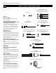
he TV’s audio/video (AV) input jacks provide
for direct picture and sound connections
between the TV and accessory devices such as
VCRs, DVD players, and others that have AV out-
put jacks.
This example, which uses the INPUT-AV 1 jacks,
shows you one way you can connect a VCR to
your TV.
Refer to the directions-for-use manual for your
VCR for further information on connections.
To make the connections shown in this example,
you will need:
• one coaxial cable (75Ω)
• one cable for a video connection (standard
RCA connector)
•two cables for audio connections (standard
RCA connectors) (only one cable is needed for
a nonstereo VCR).
NOTE: The cables are not supplied with your TV.
You should be able to buy them at most stores
that sell electronics. Or you can call our
Customer Care Center at 1-800-531-0039
1
Connect a cable TV or antenna signal to
the ANT IN jack on the rear of the VCR.
2
Connect from the OUT jack on the rear
of the VCR to the
ANTENNA IN 75Ω
jack on the rear of the TV.
3
Connect the VIDEO OUT jack on the
rear of the VCR to the INPUT AV1
VIDEO jack on the rear of the TV.
4
Connect the audio output R(ight) and
L(eft) jacks on the rear of the VCR to the
INPUT-AV 1 AUDIO jacks on the rear of
the TV.
NOTE: If the VCR is a mono (nonstereo)
unit, connect only the left audio cable,
which usually has a white connector.
5
Press the AV button on the remote con-
trol as many times as necessary to select
the AV1 source.
6
Turn the VCR on and press PLAY to
view a videotape on the TV.
You can display the AV1, AV2, or AV3 signal
sources in the PIP window. See pages 6 and 7
in the Quick Use and Setup Guide for informa-
tion on using the Picture-in-Picture (PIP) fea-
ture. The VCR connection option shown in the
Quick Use and Setup Guide will allow you to
use your VCR as a second, dedicated tuner for
viewing channels in the PIP window. Also
note that the PIP SWAP button allows you to
cc
C
HECK IT OUT
Connecting Accessory Devices to Your TV
CONNECTING A
VCR
To simplify making connections, audio and
video cables often have color-code connec-
tors. The jacks on your TV are likewise
color coded to match the connectors. The
coding is as follows:
•Yellow for video (composite)
• Red for the right audio channel
•White for the left audio channel
NOTE: If your VCR is mono (non-
stereo), you will connect only one audio
cable. You must ensure that the TV is set
to MONO for the signal source to which
you’ve connected the VCR (
INPUT-AV
1,
INPUT-AV2, or the side panel inputs
[AV3]). Otherwise, you will receive
sound from only one of the TV’s speak-
HELPFUL HINT