UOT2 Multi-role Digital Camera Head Operator’s Manual 3922 496 46751 St.
Declaration of Conformity We, Thomson Broadcast Solutions Nederland B.V., Kapittelweg 10, 4827 HG Breda, The Netherlands declare under our sole responsibility that this product is in compliance with the following standards: : Safety EN60065 EN55103-1 : EMC (Emission) EN55103-2 : EMC (Immunity) following the provisions of: a. the Safety Directives 73/23//EEC and 93/68/EEC b.
LDK 100 Triax Multi-role Digital Camera Head Operator's Manual Contents About this Manual ................................................. ii Introduction ...................................................... 1-1 Technology ........................................................ 1-2 Smart Card ........................................................ 1-3 Features ............................................................ 1-4 Important Precautions ........................................
About this Manual This operator's manual is part of a complete documentation set for the camera which also includes a Technical Manual, and a Service Manual. Purpose of this manual The purpose of this manual is to present a detailed description of how to operate the LDK 100 Multi-role Camera Head. It provides the information necessary to use the camera in different configurations and with various attachments.
Section 1 Introduction This section outlines the technology used in the LDK 100 Digital Camera Head and how this translates into a practical, useable camera. It lists the main features of the camera and also the precautions that must be taken into account when using it. Contents Technology ........................................................ 1-2 Smart Card ........................................................ 1-3 Introduction Features ............................................................
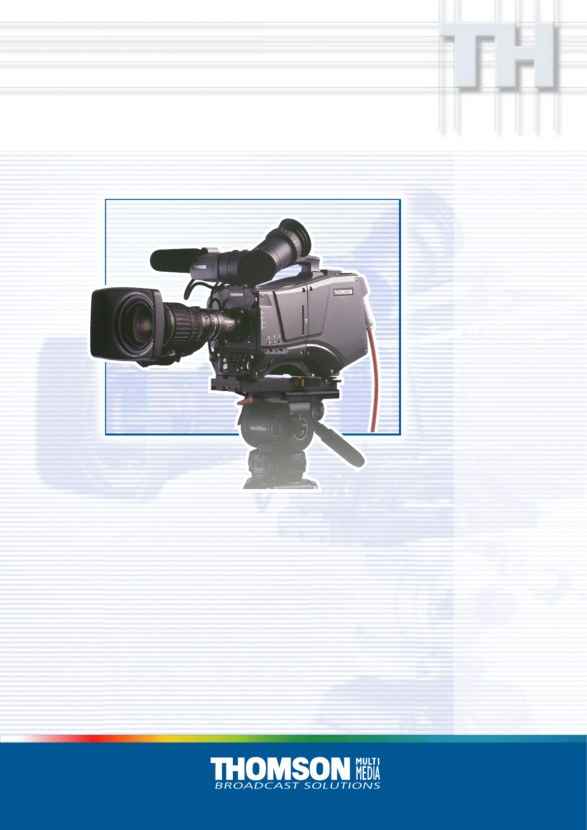
Technology The LDK 100 camera is a multi-role digital camera head using 2/3-inch CCD sensors. This is a flexible camera that is equally at home in the studio or out on location in an OB environment. Digital Processing The advanced digital processing of the camera is based on 12-bit A/D converters and more than 20-bit internal processing. Two DSPs combine all major camera functions in the digital domain, including knee, gamma, contour, matrix and colour correction.
Smart Card Three smart cards are delivered with each camera. These comprise of two user cards and one owner card. The owner's smart card has three functions: • As an access control device to the security settings of the camera. • As a storage device for four scene files. • As a storage device for two operator files. The owner card is unique to every camera. Owner card and camera must have the same serial number. The user smart card has two functions: • As a storage device for four scene files.
Features • • • • • • • • • • • • • • • • • • • 1-4 12-bit digital processing with unique software programmable video path. Superior all digital highlight handling with a wide dynamic. Unique circuitry for pivoting knee and True Colour Knee. Wide range of presets and variable 6-point digital matrix assure accurate colour matching. Fluorescent light matrix Digital gamma with unique standard preset values and highest accuracy. Digital contour with an extensive range of parameters.
Important Precautions To ensure continual high performance from the camera take the following precautions into consideration: Avoid very damp places. If the environment is wet or damp a rain cover must be used to protect the unit. Clear A 1 Clear Star 4P B 2 ND1/4 Star 6P C 3 ND1/16 Smart card Soft Focus D 4 ND1/64 VTR Save Std. File P Warnings If the unit is in a wet or damp environment, a rain cover must be used to protect it for personal safety reasons (EN60065).
1-6 Operator's Manual LDK 100 Camera Head Introduction
Section 2 Assembling the Units Section 2 provides information on the physical assembly of the camera and on how accessories can be used to expand the possibilities of the camera. The mounting of accessories and packing for transport are also explained. Contents Transport Case .................................................. 2-2 Lens ................................................................... 2-3 1.5-inch Viewfinder ............................................. 2-4 1.
Transport Case Documentation Packing inserts Top light Tripod Plate Battery Additional Supplies It is important to protect your camera against damage when transporting it. To do this, a transport case (LDK 5020/00) is optionally available for the camera, lens, viewfinder and some accessories. The camera is packed in the transport case as shown in the figure above. This ensures that the camera is not damaged during transport. 2-2 Turn the 1.
Lens 1 2 4 bts1009 3 5 To attach a lens to the camera head proceed as follows: a. Ensure that the lens locking ring 1 is in the unlocked position - turned counterclockwise. b. Remove the dust protection cap 2 . c. Slot the lens into the lens mount 3 . d. Turn the lens locking ring 1 clockwise to lock the lens in place. e. Connect the lens cable to the lens connector 4 at the right side of the camera. f.
1.5-inch Viewfinder Mounting the 1.5-inch viewfinder and microphone holder 2 1 5 4 3 To mount the 1.5-inch viewfinder proceed as follows: a. Loosen locking ring 1 of viewfinder support bracket 2 at the front of the camera handle. (As seen from the rear of the camera, turning the locking ring counterclockwise moves it towards the handle.) b. Slide the viewfinder onto the viewfinder support bracket. c.
Right eye adapter Positioning the 1.5-inch viewfinder 1 6 2 8 9 3 10 5 4 7 The horizontal position of the viewfinder can be adjusted as follows to suit your requirements: a. Loosen the locking ring 1 . (As seen from the rear of the camera, turning the locking ring counterclockwise moves it towards the handle.) b. Slide the viewfinder horizontally along the rail to the desired position. c. Tighten the locking ring 1 by turning clockwise.
1.5-inch Viewfinder Accessories Wide angle eyepiece Left eye adapter 1 1 4 3 2 3 2 If you regularly use the viewfinder at a distance, for example, when you use the camera in the hand-held position, it is recommended that you fit the optionally available wide angle eyepiece (LDK 5390/00). To fit the wide angle eyepiece proceed as follows: a. Hold the eyepiece 1 securely. b. Press the button 2 below the eyepiece tube and swing it free of the button clip 3 . c.
Microphone 5 2 1 6 3 4 7 To attach the optional microphone (AJ MC700) to the camera proceed as follows: a. Open the microphone holder by unscrewing the knurled screw 1 of the microphone support bracket 2 on the viewfinder and open. b. Slide the microphone into the split tube until the microphone shoulder reaches the mark 5 in the tube. c. Place the tube with the microphone into the holder with the split facing upwards. d.
Tripod Adapter Plate 1 5 3 4 2 To mount the camera on a tripod, the tripod plate (LDK 5030/00 is delivered as standard) must first be attached to the tripod. Follow the tripod manufacturer’s instructions to mount the wedge plate supplied with the tripod and the tripod adapter plate firmly onto the tripod. To attach the camera to the tripod adapter plate proceed as follows: a.
SuperXPander Local Control Panel Batt e nd/r e Tap ! nel ff l pa n/o ntro Ro l co VT loca 00 P1 C L n ctio Fun te era Op p /sto tart Rs VT I 1 DIGER 2 in Ga k c Bla POW The optional SuperXpander (LDK 4482) for the LDK 100 extends the camera's use in studio and EFP situations. This adapter allows larger studio lenses and a 7-inch viewfinder to be used with the camera. Additional facilities provided include a utility power outlet and a rear control panel.
Shoulder Pad Rain and Off-use Cover 1 To change the position the shoulder pad press and hold lever 1 . The shoulder pad can now be moved backwards and forwards along the axis of the camera. Adjust the shoulder pad when all units have been mounted so that the best balanced position can be obtained. The rain and off-use cover must be used when the camera system is in a wet or damp environment. This protection is necessary for personal safety reasons.
Zoom Controls Top Light 1 1 2 1 2 2 An optional zoom control unit 1 can be mounted on the carrying handle. The three available versions for different types of lens are: - LDK 6113 / 16 for Fujinon. - LDK 6113 / 26 for Canon. - LDK 6113 / 36 for Angenieux. To mount a top light 1 onto the camera, proceed as follows: a. Screw the top light 1 into either the WW1/4”-20 screw hole 2 located on the carrying handle or the screw hole 2 on the top of the microphone holder. b.
2-12 Operator’s Manual LDK 100 Camera Head Assembling the Units
Section 3 Configurations The LDK 100 Triax is a multi-role camera and this section describes how it can be used on location or in a studio environment. Information is also provided on the main video and audio signal paths through the camera head. Contents Basic Configurations ..........................................
Basic Configurations LDK 100 Operational Control Panel OCP Two-wire data cable, maximum length: 350 m (1,150 ft.) OCP THOMSON Series 9000 Cam pwr Pan lock OCP pwr Gen lock Camera Triax Base St Exposure 16 : 9 Gamma Monitoring 1 Preset 60 Hz 50 Hz Nom 1/200 1/500 1/1000 R G 2 B Var Sup Lin CVBS Seq 1 Clear Variable Clean scan 2 ND1/4 3 ND1/16 Smart card 4 ND1/64 VTR Save P Std. File Gamma wel Saw Bars Knee Base station LDK 4053 Ext.
Section 4 Location of Controls and Functions This section shows the physical location of the controls and connectors on the camera. These are grouped according to their function so as to provide a quick reference guide to the operation of a particular aspect of the camera. Contents Power Supply ..................................................... 4-2 Security and Access .......................................... 4-2 Audio ................................................................. 4-3 Intercom ....
Security and Access LDK 100 Series Power Supply 1 1 bts1311 1 Power switch 1 Smart card slot The power switch has two positions: On : Power to camera is switched on. Off : Power to camera is switched off. Insert your smart card into this slot with the chip on the card facing the front of the camera. Push the card home until it fits snugly.
Audio Intercom 1 1 1 Audio microphone connector front Balanced input connector for a high quality microphone. A phantom power supply (48V) for the microphone is provided from this socket. The gain of this audio channel can also be controlled. Location of Controls and Functions 1 Headset Programme volume control This control varies the volume of the programme intercom signal to the cameraman's headset.
Video Functions 1 2 3 11 4 10 9 8 1 Filter switch Note No optical colour filters are needed with this camera as the colour balance range is sufficient to measure temperatures from 2.5K to 20K. 5 7 2 Rotate this switch to move the optical filter wheel to its next position. The filter switch has four positions: 1 : Clear 2 : ND 1/4 filter ( 2 stops) 3 : ND 1/16 filter ( 4 stops) 4 : ND 1/64 filter ( 6 stops) The status of the filter wheel is displayed in the viewfinder for a few seconds.
4 Colour Temperature selector (White Bal.) This up/down scroll selection switch allows a choice between three preset colour temperatures: • 3200K (3.2K) - for studio lighting conditions • 5600K (5.6K) - for outdoors, clouded conditions • 7500K (7.5K) - for outdoors, clear blue skies three memory positions: • FL- memory position for fluorescent light • AW1 - memory position 1 • AW2 - memory position 2 and an automatic continuous white position: • AWC - continuous measurement (2.
12 1 2 3 11 4 10 9 5 8 10 Vertical Shift switch (V-Shift) 12 Sometimes when shooting TV screens or monitors with the same display frequency as the camera, a horizontal black bar is seen in the viewfinder because the camera is blanking while the TV is not. The V-Shift switch shifts the camera blanking. It is spring-loaded with a central rest position. Holding the switch in the + or - position moves the bar up or down so that it is no longer visible in the viewfinder.
Viewfinder 1 2 7 6 1 3 5 4 Zebra switch 5 This switch disables (OFF position) or enables the zebra pattern in the viewfinder which indicates high video levels. Values for the zebra function are selected in the VF menu. (The zebra pattern is switched off when the skin view is on.) This rotary control adjusts the sharpness of the picture displayed in the viewfinder. Reduce the crispening for a better picture when the gain is set to +++.
Viewfinder Indicators 2 1 - + ++ REC TAPE BATT ND/RE 11 10 3 4 9 5 8 3.2 5.6 7.5 FL AW1 AW2 ! 6 7 1 Gain indicators The gain indicators in the viewfinder light as follows: Gain is - (-3 or -6dB) + Gain is + (+6, +9, +12 or +18dB) ++ Gain is ++ (+9, +12,+18 or +24dB) + and ++ Gain is +++ (+30 or +36dB)[FT] (+30, +36 or 42dB)[IT] 2 Top indicators REC lights when the camera is on-air. TAPE lights when the studio ISO signal is received. BATT lights if the supply voltage is less than 11V.
Control Functions 2 1 The system menus are displayed in the viewfinder. There are two controls at the front of the camera that allow you to navigate through these menus. The functions handled by the system menus are divided into eight different menus that are listed in the main menu as follows: VF >> Lens >> Video >> Install >> Files >> Security >> Diagnostics >> Service >> 1 System Menu Rotary control This rotary control is used to move through the various menus of the control system.
4-10 Operator's Manual LDK 100 Camera Head Location of Controls and Functions
Section 5 Shooting This section contains information on the practical use of the camera using the viewfinder display and the switches at the front to control the camera. Contents Using the Camera .............................................. 5-2 Standard settings ............................................... 5-3 Colour Bar .......................................................... 5-4 Gain selection .................................................... 5-4 Optical filter selection ......................
Using the Camera The camera is operated via the viewfinder text display and the control system switches on the front panel. You have great detail and selection at your disposal when changing all the functions that are available in the camera. Refer to Section 6 - Operating the Menu System - for an explanation of the use of the menu selection structure and the viewfinder text display.
Standard settings To ensure that some of the camera functions are not set to unusual values, a standard file has been defined that contains the default values for most video functions. The table in the Appendix lists the values that are set when the standard file is recalled. Press the green STD button on the left side panel of the camera and hold it for 2 seconds to recall the standard values for the various video functions. The standard values only take effect when the camera is not on-air.
Colour Bar Optical filter selection The left side panel also contains a button for switching on the colour bar test signal. The colour bar is a standard test signal which is used to set up and check the camera before use.
Colour temperature selection For true colour reproduction the ambient lighting conditions must be compensated for by selecting a value for the colour temperature. The standard file setting is 3200K (normally used for tungsten light). Two other reference colour temperatures are available; 5600K (for outdoors, clouded conditions) and 7500K (for outdoors, clear blue skies). Three similar memory positions (FL, AW1 and AW2) are available to store the results of the auto-white measurement process.
Shooting Screens Exposure Time Sometimes when shooting TVs or computer monitors a horizontal noise bar can be seen across those screens in the viewfinder. There are two ways of removing the noise bar from the picture depending on the frame frequency of the display. For displays with the same frame frequency as the camera, for example TV sets, use the V-shift facility. For displays with a higher frame frequency, for example computer monitors, use the Clean Scan facility.
Section 6 Using the Menu System Because the LDK 100 offers such a wide range of functions, this section describes the structure of the control system. It contains procedures for controlling the menu system and explains how to program the menu system for your personal preferences. The menu structure and the methods of function selection are also explained. Contents Introduction ........................................................ 6-2 Operating the Menu System Systems Menu ............................
Introduction System Menu On/Off and selection button Rotary Control Operationally, the camera is very easy to use. However, because of the large number of functions available and the large number of set-up options, it may require some time for you to become familiar with them all. We recommend that you spend time using the various controls and displays in order to discover the wide range of possibilities.
Systems Menu The system functions of the camera are grouped into menus and sub-menus. The systems menu is viewed in the viewfinder and navigated by means of the Rotary control and the Select button which are both located at the front of the camera. Entering the Systems menu Press the Select button after the camera is switched on, the message Menu off appears in the viewfinder. Press the Select button again while this text is showing, the MAIN menu appears in the viewfinder.
Systems Menu Making changes To find out where you have to go to change a function, consult the appendix to discover under which menu group or sub-group the function you want to change is located. If the cursor points to an item (and there are no double arrows to indicate a sub-menu) then the item pointed to has a value. The value can be: a toggle value (only two values) a list value (more than two values) an analogue value (variable from 00 to 99) or unavailable (---).
Systems Menu Security Menu for Owner's Access The Security menu provides restricted access to special set-up and security features of the camera. Access to this menu requires the owner's unique smart card for the camera or the PIN code that has been set for the camera. Note An owner card is linked to the serial number of the camera and is unique to that camera. It cannot be used as an owner card for another camera. Inserting the owner card into the camera gives direct access to the security menu.
Systems Menu Files Menu Features A user of the LDK 100 camera can have access to 15 different files. This number can be extended by using additional scene file smart cards. The Files menu is used to recall and store these files. There are two types of file: * scene files * operator files. Operator files The Files menu also allows the recall of the opererator file stored in the camera (OCAM1) or one of the two operator files (OCARD1 and OCARD2) stored on the smart card.
Appendix Contents List of Abbreviations .........................................
List of Abbreviations Abbreviation A-2 Meaning Abbreviation adap agc awb adapter automatic gain control automatic white balance bal balance cam ch cont ctemp ctl cus camera channel contour colour temperature control track longitudinal customer df dyn drop frame dynamic exec exp ext ext execute exposure external extended flt fr frm f-run filter front frame free run hd hr head hour ind info interv intv ir indicator information interview interview infra-red lvl level man max mic min min m