LDK 23hs mkii High Speed Camera System Operator’s Manual 3922 496 49011 St.
Declaration of Conformity We, Thomson Broadcast Solutions Nederland B.V., Kapittelweg 10, 4827 HG Breda, The Netherlands declare under our sole responsibility that this product is in compliance with the following standards: : Safety EN60065 EN55103-1 : EMC (Emission) EN55103-2 : EMC (Immunity) following the provisions of: a. the Safety Directives 73/23//EEC and 93/68/EEC b.
LDK 23HS MkII Portable EFP - Studio High Speed Camera system Operator's Manual Contents About this Manual ................................................. ii Introduction ...................................................... 1-1 Technology ........................................................ 1-2 Features ............................................................ 1-3 Important Precautions ........................................ 1-4 Assembling the Units .......................................
About this Manual This Operator's Manual is part of a complete documentation set for the camera system which also includes an Installation and Service Manual. Purpose of this manual The purpose of this manual is to present a detailed description of how to operate the LDK 23HS mkII EFP - Studio Camera. It provides the information necessary to use the camera system in different configurations and with various attachments.
Section 1 Introduction This section outlines the technology used in the LDK 23HS mkII camera system and how this translates into a practical, useable camera system. It lists the main features of the camera system and also the precautions that must be taken into account when using it. Contents Technology ........................................................ 1-2 Features ............................................................ 1-3 Introduction Important Precautions .................................
Technology The LDK 23HS mkII is a lightweight EFP/Studio high speed camera system which uses 2/3" frame transfer sensors with Dynamic Pixel Management (DPM). Super Slow Motion Unique live slow motion capability. The LDK 23 HS mkII scans at three time the normal rate. Instead of scanning at 50 Hz for PAL and 60 Hz for NTSC the LDK 23HS mkII scans at 150 Hz for PAL and 180 Hz for NTSC. Various preset settings for artificial light conditions ensure a slow motion picture without pulsing light effects.
Features • Triple speed scanning for superb slow motion replay. • Instant replay through almost any disk based slowmotion system. • Various preset settings for artificial light conditions ensure a slow motion picture without pulsing light effects. • DPM Frame Transfer sensors with 1000 horizontal pixels in 4:3 and 16:9 aspect ratios, and the same number of vertical lines in both formats. • No change in horizontal viewing angle - so no wide angle convertors required.
Important Precautions To ensure continual high performance from the LDK 23HS mkII camera take the following precautions into consideration: Avoid very damp places. If the environment is wet or damp a raincover must be used to protect it. Do not subject the unit to severe shocks or vibration. Do not expose the camera to extremes of temperature. Do not leave the unit in direct sunlight or close to heating appliances for extended periods. Do not allow sunlight to shine into the viewfinder.
Section 2 Assembling the Units Section 2 provides information on the physical assembly of the camera system and on how accessories can be used to expand the possibilities of the camera system. The mounting of accessories and packing for transport is also explained. Contents Transport Case .................................................. 2-2 Lens ................................................................... 2-3 1.5-inch Viewfinder .............................................
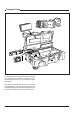
Transport Case THS 1368 It is important to protect your camera against damage when transporting it. To do this, a transport case is available for the camera, lens, viewfinder and some accessories. The camera is packed in the transport case as shown in the figure above. This ensures that the camera is not damaged during transport. Do not forget to secure the straps around the items to keep them in place.
Lens 1 H IG H S LDK2 3HS SUPE 2 PEED R SLOW mk II MOTIO N 6 5 4 3 THS1370 To attach a lens to the camera head proceed as follows: a. Ensure that the lens locking ring (1) is in the unlocked position - turned counterclockwise. b. Remove the dust protection cap (2). c. Slot the lens into the lens mount (3). d. Turn the lens locking ring (1) clockwise to lock the lens in place. e. Connect the lens cable to the lens connector (4) at the right side of the camera. f.
1.5-inch Viewfinder Mounting the optional 1.5-inch viewfinder 1 2 HI G H SP LDK23H SUPER EE D 4 S mk II SLOW MOTIO N THS 1372 3 To mount the optional 1.5-inch viewfinder proceed as follows: a. Loosen retaining screw (1) of viewfinder support bracket (2) at the front of the camera handle. b. Slide the viewfinder onto the viewfinder support bracket. c. Tighten the support bracket retaining screw (1) by turning it clockwise so that the viewfinder is mounted securely to the support. d.
Positioning the optional 1.5-inch viewfinder 2 3 1 5 THS 1374 4 The horizontal position of the viewfinder can be adjusted to suit your requirements: a. Loosen the support bracket retaining screw (1). b. Slide the viewfinder horizontally along the rail to the desired position. c. Tighten the support bracket retaining screw (1). The dioptre hood and eyepiece of the viewfinder can be rotated vertically.
Positioning the optional 1.5-inch viewfinder 1 The front-back position of the viewfinder can be adjusted to suit your requirements: a. Loosen the viewfinder front-to-back positioning lever (1). b. Slide de viewfinder longitudinally to the most convient position for viewing. c. Tighten the viewfinder front-back posititioning lever (1).
Fitting accessories to the 1.5-inch viewfinder Wide angle ocular Anti-misting Optic 2 3 1 3 2 1 If you regularly use the viewfinder at a distance, for example when you use the camera in the hand-held position, it is recommended that you fit the Wide Angle Ocular LDK 6108/10. To fit a wide angle eyepiece proceed as follows: a. Hold the eyepiece securely. b. Press the button (1) below the eyepiece tube and swing it free of the bottom clip (2). c.
Other viewfinders 5-inch viewfinder 3 1 H IG H S PEED LDK2 3HS mk II SU PER SL OW OW MO TION 2 In many EFP and studio situations the optional 5-inch viewfinder LDK 4309/15/16/55/56 is used instead of the 1.5-inch viewfinder. The 5-inch viewfinder is mounted in the slot (1) at the top-rear of the camera head. The viewfinder cable is connected to the viewfinder connector (2) at the right side of the camera. The cable is placed in the clips (3).
Microphone 1 2 D PEE H S k II H IGK23 - mMOTION LD OW R SL PE SU 01 02 3 THS 1379 To attach a microphone, the LDK 8330/00 for example, to the camera proceed as follows: a. Loosen the retaining screw (1) of the microphone support bracket (2) on the viewfinder and open. b. Place the microphone into the support bracket (2). c. Close the bracket and tighten the microphone bracket retaining screw (1). d. Connect the microphone cable to audio connector 1 or 2 at the rear of the camera. e.
Camera Tripod PHILIP S 3 2 1 2 1 To mount the optional tripod adapter LDK 5031/00 onto the tripod and the camera onto the tripod adapter proceed as follows: a. Secure the tripod adapter (1) to the tripod wedge plate using the screws supplied with the tripod. Screws with threads of 3/8 inch, M4 or M8 can be used with the tripod plate. Use two screws if possible to ensure a secure mount. b. Mount the two plates on the tripod. c.
Rain and Off-use Cover STD file CL S Bars AWB Col temp Gain Filter T The rain and off-use cover LDK 6989/00 must be used when the camera system is in a wet or damp environment. This protection is necessary for personal safety reasons. The cover can also be used indoors to protect the camera when it is used in dusty environments. It can also be useful if the camera is being put into storage. For more information on how to put on the cover refer to the User's Guide which is supplied with it.
SuperXpander STD file Bars B AW r Filte Gain THS 1383 The SuperXpander (LDK 4482) for the LDK 23HS mkII extends the camera's use in studio and EFP situations. This adapter allows larger studio lenses and a 7-inch viewfinder to be used with the camera. Additional facilities provided include a utility power outlet and a rear control panel.
Shoulder Pad Scriptboard 3 1 3 2 4 1 THS 1385 2 To mount another type of shoulder pad proceed as follows: a. Remove the two screws (1) securing the shoulder pad to the camera. b. Slide the lip (2) of the new shoulder pad under the triangular bracket (3). Use the two screws (1) to secure it in place. To mount the scriptboard LDK 6985/15 onto the camera proceed as follows: a. Secure the scriptboard to the top-rear of the camera with the retaining screw (1). b.
Top Light 2 1 To mount a toplight on the camera, proceed as follows: a. Raise the recessed bracket (1) by tightening screw (2). b. Screw or slide the toplight onto the bracket (1) and lock the toplight. c. Adjust the angle of the bracket (1) by loosening or tightening the screw (2). d. When no toplight is mounted, loosen screw (2) to lower the bracket (1) for a smooth handgrip.
Section 3 Configurations The LDK 23HS mkII is a multi-functional camera and this section describes the various ways that it can be used in a studio system with other cameras. Information on the cables, control panels and the control bus is also provided as is information on the main video and audio/intercom signal paths through the system. Contents Single camera triax mode .................................. 3-2 Multiple camera mode ........................................ 3-3 High Speed Recording ........
Single camera triax mode Two-wire data cable, maximum length: 350 m (1,150 ft.
Multiple camera mode LDK 200 Data Cable (2-wire) Maximum Length 350 m (1,150 ft) Base Station LDK 4500 Clear A 1 Clear Star 4P B 2 ND1/4 Star 6P C 3 ND1/16 Soft Focus D 4 ND1/64 VTR Save P Std. File we Smart card Prod Triax Cable Ext.
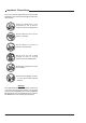
High Speed Recording Operational Control Panels OR LDK 23HS mkII OCP LDK4628 OCP LDK 4629 OR MCP LDK 4607 Master Control Panels MCP II LDK4609 CPU LDK 4058 mkII Camera Processing Unit HS mkII CAM ON CABLE TEST 0 AC ON AIR DC mains Analoque Standard Outputs Normal Scan RGB, YUV (used for live and CVBS (for monitoring) Digital Standard Output, SDI 270 Mb/s Normal Scan (Used for PGM) Digital Triple Scan For High Speed 3x SDI 270 Mb/s Ph1,2 and 3 RS 422 REMOTE Multi-Channel Disk Recorder for Su
High speed system compatibility Camera Processing Unit HS mkII + CAM ON CABLE TEST 0 AC ON AIR = 23 HS mkII operation DC mains THS 1387 23 HSmkII CPU LDK 4058 mkII version + Camera Processing Unit CAM ON CABLE TEST 0 AC ON AIR DC = 23 HS mkI operation mains THS 1387 23 HS mkII CPU LDK 4058 mkI version Camera Processing Unit HS mkII + CAM ON CABLE TEST 0 AC ON AIR DC mains = 23 HS mkI operation THS 1387 23 HS mkI CPU LDK 4058 mkII version Camera Processing Unit + CAM ON
Required Software Configurations Minimum configuration series 9000 parts System part 12NC software Status software Camera Head 3922 407 27101 44 CPU LDK4058 3922 407 27121 42 OCP LDK4628 3922 407 12151 78 OCP LDK4629 3922 407 21521 78 MCP1 LDK4607 3922 407 11411 3922 407 11421 88 88 MCP2 LDK4609 3922 407 20901 3922 407 20911 22 22 3-6 Operator's Manual LDK 23HS mkII - HS Camera System Configurations
Two-wire Data Control Bus The two-wire data bus is used to connect all control units in the Series 9000 control system. The data cable loops-through from one unit to the other. The order of connection is not important, however, the total length of the cables must not exceed 350 metres. A camera connected directly to the data bus must have its assignment number set to the number set on the OCP that is to control it.
Video Routing MONITORING + VIEWFINDER PIP OFF ON control signal control signal EXT1 EXT2 EXT EXT.
Audio/Intercom Routing AMPLIFICATION CAMERA AUDIO CHANNEL 1 AUDIO CHANNEL 2 CPU AUDIO CHANNEL 1 AUDIO CHANNEL 2 PROG HEADSET TEL. RIGHT ENG TEL. LEFT PROD FRONT/REAR TRACKER MIC CAM MIC PROD ENG TRACKER TRACKER MIC SIDE TONE CAM MIC PROD PROG ENG OFF control signal PROD Audio path The back panel of the camera has two connectors for audio microphones.
3-10 Operator's Manual LDK 23HS mkII - HS Camera System Configurations
Section 4 Location of Controls and Functions This section shows the physical location of the controls and connectors on the camera. These are grouped according to their function so as to provide a quick reference guide to the operation of a particular aspect of the camera. Contents Power Supply ..................................................... 4-2 Video Functions ................................................. 4-3 Monitoring Functions .......................................... 4-5 Viewfinder .......
Power Supply 1 3 2 THS 1390 1 Circuit breaker button (BREAKER) The circuit breaker cuts off the power when excessive current flows in the camera. Check the units for faults and if necessary take corrective action before pressing the circuit breaker button to reset it. 2 Power switch The power switch has three positions: Remote : Power is supplied via the Triax cable. Off : Power to camera is switched off. Local : Power to camera is switched off.
Video Functions 1 HIGH SPEED LDK23HS mk II SUPER SLOW SLOW MOTION MOTION THS 1391 3 2 THS 1390 1 Triaxial cable connector The triaxial cable which connects the camera to the CPU is connected to this socket. The triax cable carries all the video and control signals, and the power supply for the adapter and camera head. 2 Lens connector The flying lead from the lens is connected to this socket. Caution Do not attach the Viewfinder to the lens connector (3).
1 2 3 4 6 1 VTR switch Vertical Shift switch (V-Shift) The V-Shift switch is disabled in this mode. 3 Clean Scan button (CLS) The camera does not have a ‘clean scan’ facility. Although it is possible to select a variable exposure time between 151/181 to 829 Hz, it is not possible to increase it above the nominal setting (1/150 of 1/180). Therefore, it is not possible to eliminate the horizontal bars when shooting monitors with this camera because their refresh rates are below 150Hz.
Monitoring Functions 3 HIGH SPEED LDK23HS mk II SUPER SLOW SLOW MOTION MOTION 4 THS 1391 1 2 THS 1390 5 1 Viewfinder connector 5 Use this socket to connect the flying lead from the viewfinder to the camera. Caution Do not attach a lens to the Viewfinder connector 2 . 3 This switch is used to select the signal displayed in the viewfinder when the viewfinder signal selection switch (4) is in the EXT position. The signal displayed for each position is as follows: EXT 1 : CPU external input 1.
3 OFF 2 1 THS 1393 4 1 On-air indicator switch 4 The on-air indicator switch disables (OFF position) or enables the on-air LED indicator on the viewfinder. 2 Call switch Operating this momentary switch sends a signal to the control panels calling for attention. On-air indicators (red) The red on-air LED indicator light to indicate that the camera is on-air or recording.
Viewfinder OFF 1 THS 1393 7 8 2 3 4 THS 1373 6 1 5 Dioptric adjustment ring Turn this ring to obtain the image that is best suited to your eyesight. 2 Crispening switch Zebra switch 4 Text switch Location of Controls and Functions On-air indicators The red on-air LED indicators light to indicate that the camera is on-air or recording. The indicators can be disabled by switch 8. 8 To prevent the on-screen text from appearing in the viewfinder set this switch to the OFF position.
Viewfinder Indicators aspect ratio 4:3 aspect ratio 16:9 6 7 1 SAVE MENU BATT REC TAPE ND 31 F3.7 RE SAVE MENU BATT BATT REC TAPE ND ND RE f00 2 9 3 4 5 1 8 - + ++ AW2 AW1 3,2 5,6 Top indicators 5 BATT Function disabled. REC This red indicator lights to indicate that the camera is on-air. It flashes when any irregularity in the recording system occurs (function depends on the type of recorder). TAPE Yellow, when in triax (remote) mode: ISOindication.
Control Functions 1 THS 1392 3 2 4 1 Select switch This switch, when pressed, selects the particular menu that is pointed out by the cursor in the display or sets an on/off function. Note The MCP can select the standard file parameters as a factory or customer standard file. 4 2 Rotary control This up/down scroll switch is used to move through the various menus of the control system or to set a particular value for a function.
Audio / Intercom 1 2 3 4 5 6 7 8 9 4-10 Operator's Manual LDK 23HS mkII - HS Camera System Location of Controls and Functions
1 Intercom routing switch 8 A 3-position switch which routes the cameraman's intercom microphone signal to engineering (ENG) or production (PROD), or turns off the intercom. If the camera is used in triax mode, the momentary VTR switch at the front of the camera, on the lens or on a shot box can be used to route the cameraman's intercom microphone signal to production regardless of the position of this switch. 2 Audio Ch. 2 microphone connector Balanced input for high quality microphone.
Auxiliary Functions 1 2 3 1 4 Teleprompter output connector This BNC connector is disabled in this mode. 2 Script Light connector A 3-pole socket which supplies +12 Vdc for a script light (maximum dissipation 3W). Scriptboard LDK 6985/15 is connected to this socket. 3 Auxiliary connector This 11-pole female socket provides analogue control signals and facilities for the connection of a private data channel (see installation manual).
CPU output Functions 1 1 1 PH1 PH2 HS DSC PH3 DSC DSC 2 1 Triple scan Serial Digital video outputs The PH1, PH2 and PH3 BNC connectors provide combined a triple scan serial digital video signal to the Multi Channel disk recorder for Super Live Slow Motion. (Consult the Installation Manual of your disk recorder as required for detailed information). 2 Normal Scan Serial Digital video outputs The three DSC BNC connectors provide a normal scan serial digital video output.
4-14 Operator's Manual LDK 23HS mkII - HS Camera System Location of Controls and Functions
Section 5 Shooting This section contains information on the practical use of the camera using the viewfinder display and the switches at the front to control the camera system. Contents Using the Camera .............................................. 5-2 Standard settings ............................................... 5-2 Colour Bar .......................................................... 5-3 Gain selection .................................................... 5-3 Optical filter selection ...............
Operator's Manual LDK 23HS mkII - High Speed Camera System Using the Camera Standard settings This section describes the operational functions that are directly available, via the viewfinder display and the switches at the front and front-left. System Menu Rotary control To ensure that some of the camera functions are not set to unusual values a standard file has been defined in the factory which contains the normal values for most functions.
Colour Bar Gain selection Colour bar switch Depending on the available light levels it may be necessary to adjust the gain of the camera. Gain up/down selection switch The front/left side panel also contains a button for switching on the colour bar test signal. The colour bar is a standard test signal which is used to set up and check the camera before use.
Optical filter selection A filter can be placed in the path of the optical signal to restrict the incoming light or for artistic effect. Colour temperature selection For true colour reproduction the ambient lighting conditions must be compensated for by selecting a value for the colour temperature. The standard file setting is 3200K (normally used for tungsten light). Two other reference colour temperatures are available; 5600K (for outdoors, clouded conditions) and 7500K (for outdoors, clear blue skies).
Auto-White Balance If the three preset colour temperatures do not match your lighting conditions then the auto-white procedure must be carried out as follows: Clean Scan The camera does not have a ‘clean scan’ facility. Although it is possible to select a variable exposure time between 151/181 to 829 Hz, it is not possible to increase it above the nominal setting (1/150 of 1/180).
Artificial light conditions In artificial light conditions it is recomended to examine the lighting conditions. Standard Camera The exposure time of a Triple Scan high speed camera is a third of the exposure time of a standard camera. 1 Period Light Amplitude 1 Field Field 1 Video Level The exposure time of a standard camera corresponds with twice the lighting period. Field 2 Although the Licht is alternating each field has the same video level.
Presets for artificial lighting conditions The alternating light amplitude may cause flickering in at the Triple Scan output. There are 5 presets to accommodate different artificial lighting conditions. There are two ways to set the lighting presets; The camera systems menu and the MCP (Master Control Panel). The camera systems submenu Install \ Lighting contains the item Advanced. Set the Advanced item to the required preset to accommodate the artificial lighting condition.
5-8 Operator's Manual LDK 23HS mkII - HS Camera System Shooting
Section 6 Operating the Menu System Because the LDK 23HS mkII offers such a wide range of functions, this section describes the structure of the control system. It contains procedures for controlling the menu system and explains how to program the menu system for your personal preferences. The menu structure and the methods of function selection are also explained. Contents Introduction ........................................................ 6-2 Operating the Menu System Systems Menu ..................
Introduction Operationally, the camera is very easy to use. However, because of the large number of functions available and the large number of set-up options, it may require some time for you to become familiar with them all. We recommend that you spend time using the various controls and displays in order to discover the wide range of possibilities. Read the instructions in this section carefully but also feel free to examine the various menus in detail.
Systems Menu The system functions of the camera are grouped into menus and sub-menus. System Menu Rotary control System Menu Select button The systems menu is viewed in the viewfinder and navigated by means of the Rotary control and the Select button which are both located at the front of the camera. When you first enter a menu (other than the MAIN menu) the cursor is positioned next to the first item. The TOP and PREVIOUS entries are not immediately visible but are located above the first item.
Making changes Menu numbers To find out where you have to go to change a function, consult the appendix to discover under which menu group or subgroup the function you want to change is located. The main menus are numbered from 1 to 6. Each main function under the main menu is given a second digit (for example, the Gain under the Operate menu is given number 11, the Black function 12). In some cases a third level number is given.
VF/Lens menu As the name indicates, the functions contained under this menu control various aspects of the viewfinder and the lens. Gain The gain can be selected in four steps: -, 0, + and ++. The actual value of the gain in dB can be assigned to these symbols. This is done in the Install menu. Install menu This menu contains functions which are used to install the camera into a particular configuration.
6-6 Operator's Manual LDK 23HS mkII - HS Camera System Operating the Menu System
Appendix Contents Menu Structure ................................................. Operate Menu ................................................ Setup Menu ................................................... VF/Lens Menu ............................................... Appendix A-3 A-3 A-4 A-6 Install Menu ................................................... Diagnostic Menu ............................................ Files Menu .................................................... List of Menu Functions .
The appendix contains two tables listing the contents of the menu system. The first table presents the functions ordered in the logical divisions of the menu system itself. The table is colour coded to represent the functions that are available with different user levels. All available choices are listed for a function. The default (Def) column lists the values of the functions when a camera is delivered. If the requirements listed in the column 'Available if...
Menu Structure Menu UL Available Choices Operate 2 >> Gain Gain dB Ctemp Autowh Black MBlack Blackstr level Contour Contour 2 2 2 2 2 2 2 2 2 2 2 2 2 2 2 3 2 2 2 2 2 2 2 2 2 2 2 2 2 2 2 2 2 2 >> -6,-3,0,3,6,9,12,15,18,21,24,27,30 Contour Src Contour Lev. V-cont Noise sl Softcont Soft lev Sensor Shutter Exp.time Exp.
Menu UL Available Choices Setup(1) 2 >> Gain Gain dB Red Green Blue Black Black Auto Red Green Blue Gamma Gamma Red Master Blue Knee Knee Slope R Slope M Slope B Point R Point M Point B Limit Contour Contour Cont Src Lev.dep Co / Fine Wh. Limit Wh. Limit Master Flare Flare Red Green Blue Intercom Cam.mic Tr.
Menu UL Available Choices Setup(2) Shading Shading Shad R H saw R H par R V saw R V par R RE saw R Shad G 2 >> 4 4 4 4 4 4 4 4 >> On,Off >> 00-99 00-99 00-99 00-99 00-99 Def Available if ...
Menu UL Available Choices Vf/Lens 0-1 >> 0-1 0-1 0-1 0-1 0-1 0-1 0-1 0-1 3 3 0-1 0-1 0-1 0-1 0-1 0-1 0-1 0-1 0-1 0-1 0-1 0-1 0-1 0-1 0-1 3 3 4 3 4 4 4 4 4 4 4 4 >> Y,R,G,B Ex1,Ex2,YE1,YE2 >> On,Off,Bst 00-99 >> On,Off,Win 00-99 00-99 >> On,Off On,Off On,Off >> 00-99 On,Off On,Off On,Off >> On,Off 1,2,3,4 On,Off S,L On,Off >> Vf Inst Vf mon Vf Ext Vf Cont Vf Cont Level Zebra Zebra level contr Indicat. Zoom Ind Iris Ind Focus Ind Markers Wh.
Menu UL Available Choices Install 0-1 >> User Lev Cam Nr Timing Timing Subc Crs Subc Fine H-Phase Notch Vf Txt Mode Txt Time Dual PIP Gain Gain -= 0 += ++= Combine Diskrec Lighting Advanced Basic Appendix 0-1 2 2 2 2 2 2 2 0-1 0-1 0-1 0-1 2 2 2 2 2 2 2 2 2 2 2 0,1,2,3,4 1-15 >> CPU,On 0,90,180,270 00-99 00-99 On,Off >> On,Tim 00-99 On,Off >> -6,-3 Def Available if ...
Menu UL Available Choices Files 2 >> Filenr Recall Store 2 2 2 1-4,Std,Ins Ok,Nok,Exe Ok,Nok,Exe Menu Diagn Software Camera Battery Memory Power Comm CPU OCP MCP Boards1 Video1 Video 2 SyncShad Data Cam Vid Misc Boards 2 VideoMux AudioTxR Audio Lf Pulse Pat ShutFilt CntlUnit Boards 3 BckPanel DC Conv LLA 5" VF 7" VF A-8 Def Available if ...
List of Menu Functions Function Aspect ratio Select switch Source switch input Audio Audio 1 level select Audio 2 level select Auto lighting Auto white balance Battery status Memory Power Black Auto level Blue level Green level Red level Master Black stretch Level Switch Boards Path in Menu Operate \ Sensor Operate \ Sensor \ Asp Ratio Operate \ Sensor \ Asp Ratio Operate \ Audio Operate \ Audio Operate \ Audio Operate \ Sensor \ Shutter Operate \ Gain Diagn \ Battery Diagn \ Battery Setup \ Black Setup \
Function PIP Border Dual PIP switch Location Reverse mode Size Switch Range extender Safe area Sawtooth switch Sidetone Scene file Number select Recall switch Store switch Shading Blue Green Red White Software camera Subcarrier timing Coarse Fine Path in Menu Vf/Lens \ Vf Inst \ PIP Install \ Vf Vf/Lens \ Vf Inst \ PIP Vf/Lens \ Vf Inst \ PIP Vf/Lens \ Vf Inst \ PIP Vf/Lens \ Vf Inst \ PIP Vf/Lens \ Lens Vf/Lens \ Vf Inst \ Markers Operate \ Test Setup \ Intercom Files Files Files Setup Setup Setup Setup