LDK 5302/60 2 inch HDTV Viewfinder User’s Guide 3922 496 49001 v02
Declaration of Conformity We, Thomson Broadcast Solutions Nederland B.V., Kapittelweg 10, 4827 HG Breda, The Netherlands declare under our sole responsibility that this product is in compliance with the following standards: : Safety EN60065 EN55103-1 : EMC (Emission) EN55103-2 : EMC (Immunity) following the provisions of: a. the Safety Directives 73/23//EEC and 93/68/EEC b.
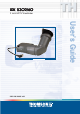
LDK5302/60 2 inch HDTV Viewfinder User's Guide The 2 Inch HDTV Viewfinder (LDK 5302/60) is a viewfinder for use with LDK 6000HD series cameras. Contents About This Manual ............................................. 1-2 Installation ......................................................... 1-3 02.38.1 Operation ........................................................... 1-6 Connectors and Cables ......................................
About This Manual Purpose of this manual The purpose of this manual is to present a global description of how to operate the viewfinder. Consult the Operator's manual of your camera as required during and after the installation process. This manual is an integral part of the service policy. It ensures that you will be able to install your viewfinder to meet the requirements of your environment.
Installation Mounting the 2-inch viewfinder and microphone holder Positioning the 2-inch viewfinder 3 2 1 1 2 3 5 4 5 4 6 To mount the 2-inch viewfinder proceed as follows: a. Loosen locking ring (1) of viewfinder support bracket (2) at the front of the camera handle. (As seen from the rear of the camera, turning the locking ring counterclockwise moves it towards the handle.) b. Slide the viewfinder onto the viewfinder support bracket. c.
Left eye adapter Wide angle eyepiece 1 1 4 3 2 3 2 If you regularly use the viewfinder at a distance, for example, when you use the camera in the hand-held position, it is recommended that you fit the optionally available wide angle eyepiece (LDK 5390/00). To fit the wide angle eyepiece proceed as follows: a. Hold the eyepiece (1) securely. b. Press the button (2) below the eyepiece tube and swing it free of the button clip (3). c. Press the button (4) above the eyepiece tube and remove the eyepiece.
Microphone 5 2 6 1 6 3 4 7 To attach the optional microphone (AJ MC700) to the camera proceed as follows: a. Open the microphone holder by unscrewing the knurled screw (1) of the microphone support bracket (2) on the viewfinder and open. b. Slide the microphone into the split tube until the microphone shoulder reaches the mark (5) in the tube. c. Place the tube with the microphone into the holder with the split facing upwards. d.
Operation 1 2 7 6 1 5 Zebra switch 3 4 5 This switch disables (OFF position) or enables the zebra pattern in the viewfinder which indicates high video levels. Values for the zebra function are selected in the VF menu. (The zebra pattern is switched off when the skin view is on.) This rotary control adjusts the sharpness of the picture displayed in the viewfinder. Reduce the crispening for a better picture when the gain is set to +++.
Viewfinder Indicators 1 - + 2 ++ REC TAPE BATT ND/RE FOC+ 3 11 10 4 9 5 8 6 3.2 4.7 5.6 7.5 FL AW1 AW2 ! 7 1 Gain indicators The gain indicators in the viewfinder light as follows: - Gain is - (-3, -6dB) + Gain is + (+3, +6, +9dB) ++ Gain is ++ (+6, +9, +12dB) + and ++ Gain is +++ (+12dB)) 2 Top indicators REC lights when the camera is on-air. TAPE lights when the studio ISO signal is received. BATT lights if the supply voltage is less than 11V.
Monitoring Functions 1 1 Tally switch 2 2 The tally switch is used to control the tally indicators at the front of the viewfinder and at the rear of the carrying handle. When this switch is set to the ON position, the tally indicators light when the camera is on-air. Tally indicators (red) The red tally indicators at the front of the viewfinder and at the rear of the carrying handle light to indicate that the camera is on-air.
Connectors and Cables Viewfinder connector 5 1 10 6 15 11 20 16 1. 2. 3. 4. 5. 6. 7. 8. 9. 10. 11. 12. 13. 14. 15. 16. 17. 18. 19. 20. -80V n.c. GND INTN-D vf ext video n.c. vf video ret SDA-D SCL-D vf ext video ret GND vf video Pb vf ret Pr vf ret GND +batt +batt Pb vf Pr vf shield 20-pin male; connector view 02.38.
1-10 User's Guide LDK 5302/60 - 2 Inch HDTV Viewfinder 02.38.