TS 870 AUTOMATIC TRANSFER SWITCHES INSTALLATION, OPERATING & SERVICE MANUAL PM062 Rev 5 08/05/05 th 9087A – 198 Street, Langley, BC Canada V1M 3B1 Telephone (604) 888-0110 Telefax (604) 888-3381 E-Mail: info@thomsontechnology.com www.thomsontechnology.
TS 870 TRANSFER SWITCH TABLE OF CONTENTS 1. PRODUCT REVISION HISTORY 1 2. EQUIPMENT STORAGE 1 2.1. 1 3. 4. 5. 6. ENVIRONMENTAL CONDITIONS NOTES TO INSTALLER 2 3.1. UPSTREAM CIRCUIT PROTECTIVE DEVICES/ELECTRICAL CONNECTIONS 2 3.2. TRANSFER SWITCHES WITH INTEGRAL OVER CURRENT PROTECTION 3 3.3. TRANSFER SWITCHES WITH MULTI-TAP VOLTAGE CAPABILITY 3 3.4. SYSTEM PHASING-HIGH LEG DELTA SYSTEMS 4 3.5. REMOTE START CONTACT FIELD WIRING 5 3.6. DIELECTRIC TESTING 5 3.7.
TS 870 TRANSFER SWITCH 9. TRANSFER SWITCH MECHANISM –1000A-1200A, T-STYLE 19 9.1. 19 MANUAL OPERATION 10. RECOMMENDED MAINTENANCE 21 11. FRONT VIEW (TYPICAL) 3 / 4 POLE 100A-250A S-STYLE TRANSFER MECHANISM 23 12. FRONT VIEW (TYPICAL) 3 POLE 400A-800A S-STYLE TRANSFER MECHANISM (MECHANISM FRONT COVER REMOVED) 24 13. FRONT VIEW (TYPICAL) 3 / 4 POLE 1000A-1200A T-STYLE TRANSFER MECHANISM 25 14. CONNECTION CONFIGURATION OPTIONS 26 15. CABLE TERMINAL INFORMATION 27 16.
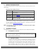
TS 870 TRANSFER SWITCH 1. PRODUCT REVISION HISTORY The following information provides an historical summary of changes made to this product since the original release. Operating & Service Manual Version Rev 0 04/11/19 Original release. Rev 1 05/03/08 Changes to incorporate reversing style ATS Motor for 100-250A transfer switches. Rev 2 05/05/26 Revisions to Section 8 and Section 18. Rev 3 06/05/08 Revisions to Section 15.
TS 870 TRANSFER SWITCH ventilated area free of corrosive agents including fumes, salt and concrete/cement dust. Apply heat as necessary to prevent condensation. 2.1.2. EQUIPMENT OPERATING The transfer switch shall be operated in an environment with a temperature range not exceeding +5° to +122° Fahrenheit (-15° to +50° Celsius) and a humidity range not exceeding 5%-95% non-condensing. 3. NOTES TO INSTALLER DANGER!!!! Arc Flash and Shock Hazard. Will cause severe injury or death.
TS 870 TRANSFER SWITCH 3.2. TRANSFER SWITCHES WITH INTEGRAL OVER CURRENT PROTECTION For models of transfer switch with integral over current protection, the over current protection must be set prior to operation. The equipment will be shipped from the factory with a longtime current setting of 100% (of the equipment rating) and maximum short- time/instantaneous current and time delay settings.
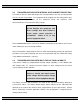
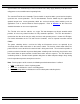
TS 870 TRANSFER SWITCH To change the transfer switch voltage, refer to “INSTRUCTIONS TO CHANGE SYSTEM VOLTAGE ON TS870 SERIES TRANSFER SWITCHES WITH TSC 80 CONTROLLER” (attached as “Appendix B). Contact Thomson Technology for further information as may be required. 3.4. SYSTEM PHASING-HIGH LEG DELTA SYSTEMS For systems using high leg delta 240V 3 phase 4 wire systems, connection of supply conductors must have the correct phasing as shown below.
TS 870 TRANSFER SWITCH the supply source be arranged such that the phase of highest potential with respect to ground is not connected to the power supply inputs to the controller (A Phase for both supplies). Failure to do so will result in equipment damage. Per NEC Article 384-3 (f) “The B phase shall be that phase having the higher voltage to ground on a 3-phase, 4-wire delta connected systems.” 3.5.
TS 870 TRANSFER SWITCH System load is then automatically re-transferred back to the utility supply following restoration of the utility power source to within normal operating limits. The standard TS 870 series Automatic Transfer Switch is rated for 100% system load and requires upstream over current protection.
TS 870 TRANSFER SWITCH 4.1. PRODUCT MODEL CODE The type of TS 870 series transfer switch supplied is identified by way of a 21 digit product code which appears on the equipment rating plate (MODEL) on the door of the transfer switch, and on the transfer switch drawings. The model code structure and definitions are as follows: 1 2 T S 1-3. SERIES TS - TRANSFER SWITCH 4 & 5. MODEL 87 - 870 SWITCH 6. POLES 2 - 2 POLE 3 - 3 POLE 4 - 4 POLE 7. CONFIGURATION TYPE A - ATS X - SPECIAL 8 - 11.
TS 870 TRANSFER SWITCH 4.2. TYPICAL COMMISSIONING PROCEDURES CAUTION: Commissioning procedures must be performed by qualified personnel only. Ensure the Automatic Transfer Switch (ATS) Control Circuit Isolation Plug is disconnected prior to energizing the supply sources. Manually place the transfer switch mechanism in the neutral position prior to applying power. Failure to do so may result in equipment failure or personal injury.
TS 870 TRANSFER SWITCH will be initiated. Once the warm-up timer expires (adjustable from 0 to 60 sec.), the Transfer to Generator Supply signal (contact closure) will be given to the transfer switch mechanism. The load will then transfer from the utility supply to the generator supply via the motor driven mechanism. The generator will continue to supply the load until the utility supply has returned.
TS 870 TRANSFER SWITCH the load to the generator supply. The utility source will be locked out and the load will remain on the generator supply until the TSC 80 alarm signal is manually reset. Refer to the TSC 80 Instruction Manual for further details on Transfer Fail operation. Should the generator power switching device trip open due to an over current condition, TSC 80 transfer controller will initiate transfer of the load to the utility supply.
TS 870 TRANSFER SWITCH switch will immediately return to the utility or generator supply if within normal operating limits. 5.2.4. ADDITIONAL PROCEDURES If the "Service Disconnected" pilot light is not illuminated, the service will not have been successfully disconnected and therefore it is not safe to perform any maintenance until the following additional procedures are performed: DANGER!!!! Arc Flash and Shock Hazard. Will cause severe injury or death.
TS 870 TRANSFER SWITCH to remove utility control power. To isolate the generator supply, remove the control circuit isolation plug. Note: The AC power conductors will still remain energized. Once all the control circuits are de-energized and isolated the "Service Disconnected" pilot light will not illuminate due to loss of control power.
TS 870 TRANSFER SWITCH 5. Attach a safety lockout padlock to the service disconnect control switch to prevent unauthorized change in operating condition and verify transfer switch door is locked closed. 6. To reenergize the load, remove the padlock(s) from the service disconnect control switch, and move the switch to the Energized position. The transfer switch will immediately return to the utility or generator supply if within normal operating limits. 5.3.
TS 870 TRANSFER SWITCH 200A, over current protection is non-adjustable thermal-magnetic type trip units. For transfer switches rated 400A through 1200A over current protection is adjustable electronic type with long time & instantaneous trip unit elements with optional ground fault protection elements. Note: Ground fault protection is supplied as standard on 1000A and 1200A transfer switches that are used on systems greater than 240V.
TS 870 TRANSFER SWITCH 7. GENERAL NOTES ON SERVICING TRANSFER SWITCH MECHANISM DANGER!!!! Arc Flash and Shock Hazard. Will cause severe injury or death. Do not open equipment until ALL power sources are disconnected This equipment must be installed and serviced only by qualified electrical personnel utilizing safe work practices and appropriate Personal Protective Equipment (PPE).
TS 870 TRANSFER SWITCH 7.3. • No moisture or other contamination is present. • Electrical conductors are adequately secured away from moving parts. To maintain operational integrity, ensure that: • All control devices are in good condition and correctly calibrated. • All control devices are adequately secured in their plug-in fixtures. Only qualified personnel should undertake Service work. Failure to correctly maintain an automatic transfer switch may present a hazard to life and equipment.
TS 870 TRANSFER SWITCH 8. TRANSFER SWITCH MECHANISM – 100A-800A, S Style The transfer mechanism consists primarily of the transfer gear motor, a drive hub assembly, and two power switching device operating arms. The reversible transfer gear motor drives the drive hub assembly, which in turn moves the power switching device operating arms. The power switching device toggles are set inside the operating arm slots and are moved by them.
TS 870 TRANSFER SWITCH Automatic operation may be regained by replacing the control circuit isolation plug. With all sources of power de-energized to the transfer switch, the control circuit isolation plug can be re-connected. The drive system will operate the transfer switch to the required position. (See manual operation instruction on front of transfer switch mechanism.
TS 870 TRANSFER SWITCH 9. TRANSFER SWITCH MECHANISM –1000A-1200A, T-Style The transfer mechanism consists primarily of the transfer motor, a hub assembly, two operating rods and two power switching device operating yokes. The reversible transfer motor drives the hub assembly, which in turn moves the operating rods that are connected to the power switching device operating yokes. The power switching device toggles are set inside the yokes and are moved by them.
TS 870 TRANSFER SWITCH connected. The drive system is self-engaging and will operate the transfer switch to the required position. (See manual operation instruction on front of transfer switch mechanism.
TS 870 TRANSFER SWITCH 10. RECOMMENDED MAINTENANCE DANGER!!!! Arc Flash and Shock Hazard. Will cause severe injury or death. Do not open equipment until ALL power sources are disconnected This equipment must be installed and serviced only by qualified electrical personnel utilizing safe work practices and appropriate Personal Protective Equipment (PPE). Failure to do so may cause personal injury or death 10.1. DO NOT perform dielectric tests on the equipment with the control components in the circuit.
TS 870 TRANSFER SWITCH 10.10. The motor and gearbox on all Transfer Mechanism styles are permanently lubricated, and should not require attention under normal operating circumstances.
TS 870 TRANSFER SWITCH 11.
TS 870 TRANSFER SWITCH 12. FRONT VIEW (TYPICAL) 3 POLE 400A-800A S-Style TRANSFER MECHANISM (Mechanism Front Cover Removed) ØC ØB ØA N N ØA ØB ØC N ØA ØB ØC CUSTOMER ORDER No. DWN BY WORK ORDER No. AUTH BY DRAWING/FILE No.
TS 870 TRANSFER SWITCH 13.
TS 870 TRANSFER SWITCH 14.
TS 870 TRANSFER SWITCH 15. CABLE TERMINAL INFORMATION TERMINAL RATING CONNECTION TIGHTNESS (In-lbs) BASIC MODEL RANGE TERMINAL MOUNTING SCREW CABLE CLAMP 1 #14-1/0 120 50 TS 87xA-0150 1 #2–4/0 120 120 TS 87xA-0200 1 #6–350MCM 150 275 TS 87xA-0250 1 #6–350MCM 150 275 1 2 2/0–500MCM 72 275 1 2 2/0–500MCM 72 275 1 3 2/0–500MCM 110 375 1 4 4/0–500MCM 375 375 QTY PER PHASE TS 87xA-0100 TS 87xA-0400 TS 87xA-0600 TS 87xA-0800 TS 87xA-1200 1.
TS 870 TRANSFER SWITCH 16.2. INTERRUPTING CAPACITY CURRENT RATINGS (ALL MODELS WITH INTEGRAL OVERCURRENT PROTECTION OPTION) INTERRUPTING CAPACITY CURRENT RATING AMPS (RMS) 1 No Upstream Circuit Breaker Protection Required @240V @480V @600V BASIC MODEL MAX.
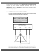
TS 870 TRANSFER SWITCH The interconnected system shall be evaluated to ensure compliance with the appropriate schematic drawings. The proper location of sensors and power cabling shall be determined. The grounding points of the system shall be verified to determine that ground paths do not exist that would bypass the sensors. The use of high-voltage testers and resistance bridges may be required. A simulated fault current is to be generated by a coil around the sensors.
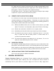
TS 870 TRANSFER SWITCH 18. TROUBLESHOOTING DANGER!!!! Arc Flash and Shock Hazard. Will cause severe injury or death. Do not open equipment until ALL power sources are disconnected This equipment must be installed and serviced only by qualified electrical personnel utilizing safe work practices and appropriate Personal Protective Equipment (PPE).
TS 870 TRANSFER SWITCH - Transfer to generator source without a power failure in the utility source - - Defective TSC 80 controller (verify output signals with circuit board mounted diagnostic LED’s) TSC 80 has “Transfer Fail” alarm activated as indicated by flashing Load on Generator LED. Determine cause of alarm and rectify before TSC 80 is reset A test mode has been activated (check TSC 80 status LED) Utility supply voltage is slightly below voltage sensing setpoints.
TS 870 TRANSFER SWITCH NOTE There are no user serviceable components located on the TSC 80 printed circuit board. If the TSC 80 controller is deemed to be defective it must be returned to the Thomson Technology Factory for repair or replacement. Please refer to Product Return Policy section of this manual further information on product return procedures required. 19.
TS 870 TRANSFER SWITCH Component Description Thomson Technology Part Number (100A-250A S Style Mechanism) 120V 20 watt 1 PH Comments assembly. Contact Thomson Technology Service Department for installation procedures Transfer Switch Motor (400A-800A S Style Mechanism) 120V 30 watt 1 PH 007961 Motor is supplied with gear box assembly.
TS 870 TRANSFER SWITCH 21.
TS 870 TRANSFER SWITCH 22. PERFORMANCE TEST FORM This form should be retained by those in charge of the building electrical installation in order to be available to the authority having jurisdiction.
APPENDIX “A” THOMSON TECHNOLOGY© TYPICAL AUTOMATIC TRANSFER SWITCH COMMISSIONING PROCEDURES Model Series TS 870 Note: The following commissioning procedures are provided for general information only pertaining to typical site installations and applications. Contact the equipment supplier for further information as may be required. DANGER!!!! Arc Flash and Shock Hazard. Will cause severe injury or death.
APPENDIX “A” THOMSON TECHNOLOGY© TYPICAL AUTOMATIC TRANSFER SWITCH COMMISSIONING PROCEDURES Model Series TS 870 3) For 240V High Leg Delta systems refer to the ATS instruction manual for correct phasing required and re-configuring procedures. CAUTION: FAILURE TO OBTAIN THE CORRECT ATS PHASING WILL RESULT IN EQUIPMENT MALFUNCTION AND DAMAGE. 4) Confirm cable size is correct for the lugs supplied in the transfer switch (line and load).
APPENDIX “A” THOMSON TECHNOLOGY© TYPICAL AUTOMATIC TRANSFER SWITCH COMMISSIONING PROCEDURES Model Series TS 870 iii) Green “Load” LED is “ON” 10) To verify all LED’s are operational, perform a “LAMP TEST” operation (lamp test is initiated by pressing and holding the 2 push buttons on the TSC 80 faceplate simultaneously “ON” until all the LED’s change state).
APPENDIX “A” THOMSON TECHNOLOGY© TYPICAL AUTOMATIC TRANSFER SWITCH COMMISSIONING PROCEDURES Model Series TS 870 Hold the push button “ON” for approximately 5 seconds until the LED light changes state. Once the mode is initiated, the engine will immediately start and the generator will transfer on load as previously described. Note: The generator may or may not transfer on load, which is dependent on the TSC 80 configuration setting. The factory default setting is for a “Load Transfer” plant exercise test.
APPENDIX “B” THOMSON TECHNOLOGY© INSTRUCTIONS TO CHANGE SYSTEM VOLTAGE ON TS 870 SERIES TRANSFER SWITCHES WITH TSC 80 CONTROLLER DANGER!!!! Arc Flash and Shock Hazard. Will cause severe injury or death. Do not open equipment until ALL power sources are disconnected This equipment must be installed and serviced only by qualified electrical personnel utilizing safe work practices and appropriate Personal Protective Equipment (PPE). Failure to do so may cause personal injury or death 1.
APPENDIX “B” THOMSON TECHNOLOGY© INSTRUCTIONS TO CHANGE SYSTEM VOLTAGE ON TS 870 SERIES TRANSFER SWITCHES WITH TSC 80 CONTROLLER TSC 80 Printed Circuit Board 600V 480V 380V 240V 50HZ 1 Phase No Xfer Secure 38 SYSTEM VOLTAGE JUMPERS JP5 44 TB7 Gen Warmup Figure 1 th Figure 2 9087A - 198 Street, Langley, B.C.