UOT2 Triax Adapter for LDK 200 Series Operator’s Manual 3922 496 47971 St.
Declaration of Conformity We, Thomson Broadcast Solutions Nederland B.V., Kapittelweg 10, 4827 HG Breda, The Netherlands declare under our sole responsibility that this product is in compliance with the following standards: : Safety EN60065 EN55103-1 : EMC (Emission) EN55103-2 : EMC (Immunity) following the provisions of: a. the Safety Directives 73/23//EEC and 93/68/EEC b.
LDK 200 Triax Multi-role Camera Operator's Manual Contents About this Manual ................................................. ii Introduction ............................................................... 1-1 Technology ........................................................ 1-2 Smart Card ........................................................ 1-3 Features ............................................................ 1-4 Important Precautions ........................................
About this Manual This operator's manual is part of a complete documentation set for the camera which also includes a Technical Manual, and a Service Manual. Structure of this manual Purpose of this manual Section 1: Introduction The purpose of this manual is to present a detailed description of how to operate the LDK 200 Multi-role Camera equipped with an LDK 5430 Triax Adapter. It provides the information necessary to use the camera in different configurations and with various attachments.
Section 1 Introduction This section outlines the technology used in the LDK 200 Triax camera and how this translates into a practical, useable camera. It lists the main features of the camera and also the precautions that must be taken into account when using it. Contents Technology ........................................................ 1-2 Smart Card ........................................................ 1-3 Introduction Features ............................................................
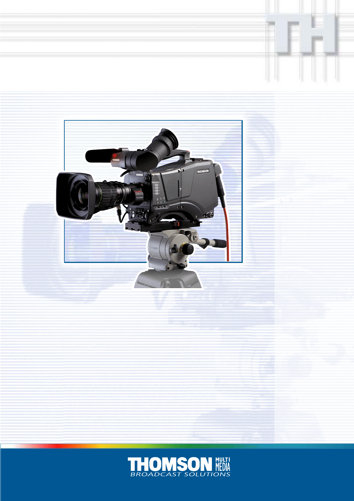
Technology The LDK 200 Triax camera combines a multi-role digital camera head using 2/3-inch CCD sensors with a triax adapter. The result is a flexible camera that is equally at home in the studio or out on location in an OB environment. Camera Head The Frame Transfer CCD DPM sensor offers superior performance and can handle highlights of up to 600%. The 2/3-inch sensors have a high dynamic range and high linear sensitivity over all camera lens apertures.
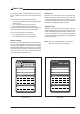
Smart Card Three smart cards are delivered with each camera. These comprise of two user cards and one owner card. The owner's smart card has three functions: • As an access control device to the security settings of the camera. • As a storage device for four scene files. • As a storage device for two operator files. The owner card is unique to every camera. Owner card and camera must have the same serial number. The user smart card has two functions: • As a storage device for four scene files.
Features • • • • • • • • • • • • • • • • 1-4 3x 2/3-inch switcheable DPM sensors ensure no vertical smear. DPM Frame Transfer sensors with 1000 horizontal pixels in 4:3 and 16:9 aspect ratios, and the same number of vertical lines in both formats. No change in horizontal viewing angle - so no optical wide angle convertors required. 12-bit digital processing with unique software programmable video path. Superior all digital highlight handling with a wide dynamic range.
Important Precautions To ensure continual high performance from the camera take the following precautions into consideration: Avoid very damp places. If the environment is wet or damp a rain cover must be used to protect the unit. Clear A 1 Clear Star 4P B 2 ND1/4 Star 6P C 3 ND1/16 Smart card Soft Focus D 4 ND1/64 VTR Save Std. File P Ext. Iris WARNINGS If the unit is in a wet or damp environment, a rain cover must be used to protect it for personal safety reasons (EN60065).
1-6 Operator's Manual LDK 200 Triax Introduction
Section 2 Assembling the Units Section 2 provides information on the physical assembly of the camera and on how accessories can be used to expand the possibilities of the camera. The mounting of accessories and packing for transport are also explained. Contents Transport Case .................................................. 2-2 Lens ................................................................... 2-3 1.5-inch Viewfinder ............................................ 2-4 1.
Transport Case Cle Sta ar A r 4P Sta Sof r 6P t foc us B C D ar 1 Cle 1 ND 1 ND 1 ND 1/4 1/1 6 1/6 4 Documentation Packing inserts Top light Tripod Plate Battery Additional Supplies It is important to protect your camera against damage when transporting it. To do this, a transport case (LDK 5020/00) is optionally available for the camera, lens, viewfinder and some accessories. The camera is packed in the transport case as shown in the figure above.
Lens 1 2 bts1009 4 3 5 To attach a lens to the camera head proceed as follows: a. Ensure that the lens locking ring 1 is in the unlocked position - turned counterclockwise. b. Remove the dust protection cap 2 . c. Slot the lens into the lens mount 3 . d. Turn the lens locking ring 1 clockwise to lock the lens in place. e. Connect the lens cable to the lens connector 4 at the right side of the camera. f.
1.5-inch Viewfinder Mounting the 1.5-inch viewfinder and microphone holder Positioning the 1.5-inch viewfinder 3 1 2 1 2 3 5 4 5 4 6 To mount the 1.5-inch viewfinder proceed as follows: a. Loosen locking ring 1 of viewfinder support bracket 2 at the front of the camera handle. (As seen from the rear of the camera, turning the locking ring counterclockwise moves it towards the handle.) b. Slide the viewfinder onto the viewfinder support bracket. c.
1.5-inch Viewfinder Accessories Wide angle eyepiece Left eye adapter 1 1 4 3 2 3 2 If you regularly use the viewfinder at a distance, for example, when you use the camera in the hand-held position, it is recommended that you fit the optionally available wide angle eyepiece (LDK 5390/00). To fit the wide angle eyepiece proceed as follows: a. Hold the eyepiece 1 securely. b. Press the button 2 below the eyepiece tube and swing it free of the button clip 3 . c.
Other Viewfinders Zoom Controls 1 1 2 ar A ar Cle PB r4 Sta 6P r Sta C sD 1 Cle 1/4 2 3 4 ND 6 ND ND 1/1 4 1/6 cu ft fo So In many EFP and studio situations the optional 5-inch viewfinder (LDK 5310) is used instead of the 1.5-inch viewfinder. The 5-inch viewfinder is mounted in the quick mount shoe 1 at the top-rear of the camera head. Slide the viewfinder foot into the bracket until it clicks into place.
Microphone 5 2 6 1 6 3 4 7 To attach the optional microphone (AJ MC700) to the camera proceed as follows: a. Open the microphone holder by unscrewing the knurled screw 1 of the microphone support bracket 2 on the viewfinder and open. b. Slide the microphone into the split tube until the microphone shoulder reaches the mark 5 in the tube. c. Place the tube with the microphone into the holder with the split facing upwards. d.
Tripod Adapter Plate Clear A 1 Clear Star 4P B 2 ND1/4 Star 6P C 3 ND 1/16 Soft focus D 4 ND 1/64 1 5 3 4 2 To mount the camera on a tripod, the tripod plate (LDK 530/00 is delivered as standard) must first be attached to the tripod. Follow the tripod manufacturer’s instructions to mount the wedge plate supplied with the tripod and the tripod adapter plate firmly onto the tripod.
SuperXPander I 21 G I R DWE PO The optional SuperXpander (LDK 4482) for the LDK 100 extends the camera's use in studio and EFP situations. This adapter allows larger studio lenses and a 7-inch viewfinder to be used with the camera. Additional facilities provided include a utility power outlet and a rear control panel.
Shoulder Pad Rain and Off-use Cover 1 To change the position the shoulder pad press and hold lever 1 . The shoulder pad can now be moved backwards and forwards along the axis of the camera. Adjust the shoulder pad when all units have been mounted so that the best balanced position can be obtained. The rain and off-use cover must be used when the camera system is in a wet or damp environment. This protection is necessary for personal safety reasons.
Script board Top Light 1 2 3 1 A Clear 1 Clear B Star 4P 2 ND1/4 C Star 6P 3 ND 1/16 sD 4 ND 1/64 Soft focu Clear A 1 Clear Star 4P B 1 ND1/4 Star 6P C 1 ND 1/16 Soft focus D 1 ND 1/64 4 1 3 2 A Cl ar To mount the optional Script board (LDK 6985/21) onto the camera proceed as follows: a. Secure the Script board to the top-rear of the camera with the quick mount adapter 1 . b. Connect Script board light cable to the script light connector 2 at the rear of the camera.
2-12 Operator’s Manual LDK 200 Triax Assembling the Units
Section 3 Configurations The LDK 200 Triax is a multi-role camera and this section describes how it can be used on location or in a studio environment. Information is also provided on the main video and audio signal paths through the camera head. Contents Basic Configurations ..........................................
Basic Configurations Operational Control Panel OCP LDK 200 Two-wire data cable, maximum length: 350 m (1,150 ft.) OCP THOMSON Series 9000 Cam pwr Pan lock OCP pwr Gen lock Camera Triax Base St Exposure 16 : 9 Gamma Monitoring 1 Preset 60 Hz 50 Hz Nom 1/200 1/500 1/1000 R G 2 Var B Lin Sup CVBS Seq Variable Clean scan Clear A 1 Clear Star 4P B 2 ND1/4 Gamma Star 6P C 3 ND1/16 Soft Focus D 4 ND1/64 VTR Save P Std.
Section 4 Location of Controls and Functions This section shows the physical location of the controls and connectors on the camera. These are grouped according to their function so as to provide a quick reference guide to the operation of a particular aspect of the camera. Contents Power Supply .................................................... 4-2 Security and Access ......................................... 4-3 Video Functions .................................................
A 1 PB 2 ND1/4 PC 3 ND 1 cus D 4 ND 1 Star 4 Star 6 Soft fo Front Ext Mix Loc Progr Rear Eng Clear Clear Eng Off Prod Prod Power Supply Call CVBS (option) 6 /16 /64 Mic Ext VF Front Rear 48V Scrip Light DC in Breaker 5 Power on TP 48V On Ext 1 Ext 2 12V 1,5A DC Out Mic 2 2 4 3 1 1 1 Power switch The power switch has two positions: On : Power to camera is switched on. Off : Power to camera is switched off.
Security and Access A 1 Clear 4P B 2 ND1/4 6P C Star 3 ND 1/1 Soft D 4 focus LDK 100 Series Clear Star 6 4 ND 1/6 1 1 1 Smart card slot Insert your smart card into this slot with the chip on the card facing the front of the camera. Push the card home until it fits snugly. There are two types of card; an owner card and a user card. Both cards store operator files and scene files. The owner card can be used to change the user level Location of Controls and Functions of the camera.
Video Functions 1 2 Clear A 1 Clear B 2 ND1/ Star 4P Star 6P Soft C 3 D 4 focus 4 3 16 ND 1/ 64 ND 1/ 4 12 5 11 6 10 9 1 1 Filter switches 7 8 2 Rotate these two switches to move the optical filter wheels.
but the non-standard indicator (!) lights. 3 3 Std Scene File button The standard scene file button is a momentary button which, when pressed for two seconds, recalls the standard scene file video values. These values do not take effect immediately if the camera is on air; they take effect when the camera goes off air. Refer to the Appendix for the default values of the factory defined standard scene file. Refer to Section 6 to find out how to define and assign a standard customer scene file.
1 2 Clear A 1 Clear B 2 ND1/ Star 4P Star 6P Soft C 3 D 4 focus 4 3 16 ND 1/ 64 ND 1/ 4 12 5 11 6 10 9 position. Refer to Section 5 for more information on how to use the automatic white balance. Note: Black balance is not necessary with this camera because of the continuous automatic black control circuits. 10 7 8 10 Exposure Time switch This up/down momentary switch gives a choice of eight exposure time settings. These are: Nom. - nominal setting Cl.
Monitoring Functions Eng Off Prod Front Ext Mix Loc Prod 6 5 Eng Progr Rear Call CVBS (option) 1 Mic VF Ext Front Rear 48V 2 7 Scrip Light Breaker DC in Power on 3 TP 8 48V On Ext 1 Ext 2 12V 1,5A DC Out Mic 2 4 1 1 CVBS output connector This BNC connector provides a 1Vpp CVBS output signal when the optional encoder (LDK 5405/00 for PAL or LDK 5405/50 for NTSC) is fitted.
Viewfinder 1 2 7 3 6 5 1 1 Zebra switch 4 5 This switch disables (OFF position) or enables the zebra pattern in the viewfinder which indicates high video levels. Values for the zebra function are selected in the VF menu. (The zebra pattern is switched off when the skin view is on.) 2 Option switch This switch is included on the viewfinder to allow future features to be incorporated.
Viewfinder Indicators 1 - + 2 ++ REC TAPE BATT ND/RE 3 11 10 4 9 5 8 3.2 5.6 7.5 FL AW1 AW2 ! 6 7 1 2 Gain indicators 6 The gain indicators in the viewfinder light as follows: Gain is - (-3 or -6dB) + Gain is + (+6, +9, +12 or +18dB) ++ Gain is ++ (+9, +12,+18 or +24dB) + and ++ Gain is +++ (+30 or +36dB) 2 2 Top indicators 3 3 Iris indication Indicates the value of the iris opening (when enabled in the VF menu).
Eng Off Prod Front Ext Mix Loc Prod Audio Progr Rear 2 Eng Call CVBS (option) Mic VF Ext Front Rear 48V Scrip Light DC in Breaker 3 Power on TP 48V On Ext 1 Ext 2 12V 1,5A DC Out Mic 2 4 1 5 1 1 Audio microphone connector front Balanced input connector for a high quality microphone. A phantom power supply (48V) for the microphone is provided from this socket. The gain of this audio channel can also be controlled.
Intercom 1 2 3 Eng Off Prod Front Ext Mix Loc Prod 4 5 Progr Rear Eng Call Clear 2 r 4P B ND1/ 4 Sta CVBS (option) Star 6P Soft C 3 D 4 focus 16 ND 1/ 64 ND 1/ 6 Mic VF A 1 Clear Ext Front Rear 48V Scrip Light Breaker DC in Power on TP 48V On Ext 1 Ext 2 7 12V 1,5A DC Out Mic 2 1 1 Intercom routing switch 4 A 3-position switch that routes the camera operator intercom microphone signal to engineering (ENG) or production (PROD), or turns off the intercom.
Control Functions Clear A 1 PB 2 ND1/4 PC 3 ND 1 Star 4 Star 6 Soft Clear D 4 focus /16 /64 ND 1 2 1 The system menus are displayed in the viewfinder. There are two controls at the front of the camera that allow you to navigate through these menus.
Auxilary Functions 1 Eng Off Prod Front Rear Tracker Loc Ext Mix Aux Call CVBS (option) 4 Mic VF 5 Ext Front Rear 48V Scrip Light Breaker 2 DC in Power on TP REF IN 48V On Ext 1 E 3 6 1 1 Call button Pressing this momentary button sends a signal to the control panels calling for attention. 2 2 3 4 Aux connector This 11-pole female socket provides analogue control signals and facilities for the connection of a private data channel (see installation manual).
4-14 Operator's Manual LDK 200 Triax Location of Controls and Functions
Section 5 Shooting This section contains information on the practical use of the camera using the viewfinder display and the switches at the front to control the camera. Contents Using the Camera .............................................. 5-2 Standard settings ............................................... 5-3 Colour Bar .......................................................... 5-4 Gain selection .................................................... 5-4 Optical filter selection ......................
Using the Camera The camera is operated via the viewfinder text display and the control system switches on the front panel. You have great detail and selection at your disposal when changing all the functions that are available in the camera. Refer to Section 6 - Operating the Menu System - for an explanation of the use of the menu selection structure and the viewfinder text display.
Standard settings To ensure that some of the camera functions are not set to unusual values, a standard file has been defined that contains the default values for most video functions. The table in the Appendix lists the values that are set when the standard file is recalled. Press the green STD button on the left side panel of the camera and hold it for 2 seconds to recall the standard values for the various video functions. The standard values only take effect when the camera is not on-air.
Colour Bar Optical filter selection The left side panel also contains a button for switching on the colour bar test signal. The colour bar is a standard test signal which is used to set up and check the camera before use.
Colour temperature selection For true colour reproduction the ambient lighting conditions must be compensated for by selecting a value for the colour temperature. The standard file setting is 3200K (normally used for tungsten light). Two other reference colour temperatures are available; 5600K (for outdoors, clouded conditions) and 7500K (for outdoors, clear blue skies). Three similar memory positions (FL, AW1 and AW2) are available to store the results of the auto-white measurement process.
Shooting Screens Sometimes when shooting TVs or computer monitors a horizontal bar can be seen across those screens in the viewfinder. There are two ways of removing the noise bar from the picture depending on the frame frequency of the display. For displays with the same frame frequency as the camera, for example TV sets, use the V-shift facility. For displays with a higher frame frequency, for example computer monitors, use the Clean Scan facility.
Exposure Time The exposure time values of 1/200, 1/500 and 1/1000 of a second are used to capture fast moving objects so that these can be played back sharply in slow motion. The value selected depends on the speed of the moving object. Note: Increasing the exposure speed lowers the camera sensitivity proportionally. The exposure selection also includes lighting control positions which can be used when shooting with lighting that is operating at a different frequency to the camera.
5-8 Operator's Manual LDK 200 Triax Shooting
Section 6 Using the Menu System Because the LDK 200 offers such a wide range of functions, this section describes the structure of the control system. It contains procedures for controlling the menu system and explains how to program the menu system for your personal preferences. The menu structure and the methods of function selection are also explained. Contents Introduction ........................................................ 6-2 Operating the Menu System Systems Menu ............................
Introduction Operationally, the camera is very easy to use. However, because of the large number of functions available and the large number of set-up options, it may require some time for you to become familiar with them all. We recommend that you spend time using the various controls and displays in order to discover the wide range of possibilities. Read the instructions in this section carefully but also feel free to examine the various menus in detail.
Systems Menu The system functions of the camera are grouped into menus and sub-menus. The systems menu is viewed in the viewfinder and navigated by means of the Rotary control and the Select button which are both located at the front of the camera. The TOP and PREVIOUS entries are not immediately visible but are located above the first item. Use the Rotary control to scroll up to them. TOP PREVIOUS Entering the Systems menu Lens type Auto Iris Peak/Average Auto iris setp. Mom. iris setp.
Systems Menu Making changes Menu Structure To find out where you have to go to change a function, consult the appendix to discover under which menu group or sub-group the function you want to change is located. Access to the functions on these menus is determined by the user level that has been set. The menus are as follows: Main (top) menu If the cursor points to an item (and there are no double arrows to indicate a sub-menu) then the item pointed to has a value.
Systems Menu Security Menu for Owner's Access PIN Code The Security menu provides restricted access to special set-up and security features of the camera. The PIN code of the camera can be viewed and changed in the Security menu. Access to this menu requires the owner's unique smart card for the camera or the PIN code that has been set for the camera. The camera's PIN code when it leaves the factory is set to 0000. It is strongly advised that this code be changed by the owner on receipt of the camera.
Systems Menu Files Menu Features Install Menu Features A user of the LDK 200 camera can have access to 15 different files. This number can be extended by using additional scene file smart cards. The Files menu is used to recall and store these files. There are two types of file: * scene files * operator files. Gain A scene file contains values related to the picture performance. The operator file contains values related to the set-up of the camera (viewfinder, lens and installation parameters).
Appendix Contents System Menu Structure .................................... A-3 List of System Menu Functions .......................A-17 Appendix List of Abbreviations ........................................
The appendix contains two types of table listing the contents of the menu system. A list of abbreviations is also included. The System Menu tables present the functions ordered in the logical divisions of the menu system itself with additional information in the columns: • User level column The User level column indicates the functions that are available with different user levels. • Values column All available choices are listed for a function.
System Menu Structure MAIN Menu Menu text VF Lens Video Install Files Security Diagnostics Service Appendix User level >> >> >> >> >> >> >> >> 0 1 2 0 1 2 2 0 1 2 1 2 0 1 2 2 3 3 3 3 3 3 3 3 Values Blocked if File Default S S S S S S S S Camerahead Software Status 37 A-3
VF Menu Menu text VF mon VF Contour VF Contour Level Zebra Zebra zebra mode zebra level (%) zebra contrast Centre Cross Safe Area Audio Bar Box downright Iris Ind. Focus Ind. Zoom Ind. User level Values File Default 2 3 S Y,R,G,B - operator Y 2 3 2 3 S On, Off S 0..99 VF cont. Off operator operator On 95 >> >> 0 0 0 0 0 0 0 1 1 1 1 1 1 1 2 2 2 2 2 2 2 3 3 3 3 3 3 3 3 3 3 3 S S S S S S S S S S S On,Off Level, band 0..99 0..
LENS Menu Menu text Lens Type Auto Iris Peak/Average AutoIris Setpoint Mom. Iris Setpoint Manufacturer Extended iris GainSpeed ExpTimeSpeed Min iris Max iris Min exp time Max Gain (dB) Autoiris const Iris gain VTR Switch Appendix User level >> >> 0 1 2 3 0 1 2 3 3 3 3 0 1 2 3 3 3 3 3 3 3 3 0 1 2 3 S S S S S S S S S S S S S S S S Values Std,WA On, Off 0..99 0..99 0..99 Fuj1,Fuj2, Ang, Can, 0..99 0..99 F5.6, 8, 11, 16 F1.4, 2, 2.8, 4, 5.6 1/100, 1/200, 1/500 0..15 (steps of 3) 5..
VIDEO Menu Menu text User level 2 3 Colour filter Contour Contour Level Source Select vert cont coarse/fine Level level dep. noise slicer Soft Contour Soft Contour Level Knee Contour Skin Skin Auto View Skin Level width1 Red width1 Blue color1 Red color1 Blue width2 Red width2 Blue color2 Red color2 Blue Flare Flare Red Green Blue Black Dyn. Black Black strech Master Red Green Blue Master A-6 Values S 00 ..
VIDEO Menu (continued) Menu text Gain Red Green Blue Knee Knee Knee Type Slope M Point M Knee Limit Desaturation Desat Level Auto Point Auto Ref Gamma Gamma Master Red Green Blue User level Blocked if File Default >> 2 3 2 3 2 3 S 0..99 S 0..99 S 0..99 - scene scene scene 50 50 50 2 3 3 3 3 S S S S Off, Auto, Var Y, NAM 0..99 0..99 knee <> var knee <> var scene scene scene scene Off Y 60 50 S S S S S 0..99 Off, On 0..99 0..99 0..
VIDEO Menu (continued) Menu text Shading Shading H saw red H saw green H saw blue H par red H par green H par blue V saw red V saw green V saw blue V par red V par green V par blue A-8 User level Values Blocked if File Default Shading = Off Shading = Off Shading = Off Shading = Off Shading = Off Shading = Off Shading = Off Shading = Off Shading = Off Shading = Off Shading = Off Shading = Off scene - >> S S S S S S S S S S S S S Off, On 0..99 0..99 0..99 0..99 0..99 0..99 0..99 0..99 0..99 0..99 0..
INSTALL Menu LDK 5411 Betacam Adapter Menu text Disable Camera IR receiver OnAir Lamp Timing * subc. Course subc. Fine H. phase Notch * Aspect Ratio select loc/ext Exposure Lighting Clean Scan Cl.
INSTALL Menu LDK 5400 Triax Adapter Menu text Disable Camera IR receiver OnAir Lamp Intercom SideTone Cam. Mic Gain Cam. Mic Power Audio User level 0 0 0 0 0 0 0 Units Gain preset (dB) Gain (dB) Gain + (dB) Gain ++ Gain +++ (dB) Autowhite Awb speed Awb gain Quick Smart Touch A-10 2 2 2 2 2 2 2 3 3 3 3 3 3 3 S S S S S S S Off, On Off, On Off, On 0..99 0..
INSTALL Menu LDK 5430 Triax Adapter Menu text Disable Camera IR receiver OnAir Lamp Intercom Side tone Cam. Mic Cam. Mic Gain Cam. Mic Power Cam. Production Cam. Engeneering Cam. Program Cam. Track Cam. Track level Track Mic To Track Mic Gain Track Mic Power Track Source Cam. Mic To Audio User level 0 1 2 3 0 1 2 3 0 1 2 3 S Off, On S Off, On S Off, On S S S S S S S S S S S S S S Audio 1 Gain 1 2 3 S Audio 1 HPF 1 2 3 Audio 2 Gain 1 2 3 Audio 2 HPF Timing subc. Coarse subc. Fine H.
INSTALL Menu LDK 5430 Triax Adapter (continued) Menu text Autowhite Awb speed Awb gain Quick Smart Touch User level >> 1 2 3 S 0..99 S 0..99 S On, Off S TP, Aux TP/Aux video Tracker Channel * Prog Channel * Values 0 1 2 3 0 1 2 3 S Inter, Priva S Inter, Priva Blocked if File Coltemp<>AW operator operator not installed - Default 4 10 On No LDK4500 Basestation - - - operator operator Inter Inter * If a LDK 4500 Basestation is used this item is only an indication of the Basestation settings.
FILES Menu Menu text Store scenefile User level Recall Store oper. file File select Store Recall oper.
SECURITY Menu Menu text User level Installed Level Run Hours Days ago Set Time Hour Minute Set Date Year Month Day PIN code Four digits Customer files Store cust. Scene Store cust. Oper Store cust. VTR Green Button Standard Scene file Operator file VTR file A-14 Values 2 3 S user0..user3 2 3 Blocked if - u3 S 0 ...
DIAGNOSTICS Menu Menu text Communication Base Station OCP MCP Adaptor Type Sensor Type Sensor Voltage Shutter Run Front Power Green carrier Cam. 12nc Cam. Version Cam. Status Cam. Boot ver. Cam. FPGA ver. Adapter 12nc Adapter Version Adapter Status Appendix User level Values >> 2 2 2 2 2 2 2 2 2 2 3 3 3 3 3 3 3 3 3 3 2 2 2 2 3 3 3 3 2 3 S S S S S S S S S S S S S S S S S Ok, NotOk Ok, NotOk Ok, NotOk Triax, DVCPRO, ..... IT,ITW,FT,DPM Ok, NotOk Run, Stop Ok, NotOk Ok, NotOk ... ... ... ... ... ...
SERVICE Menu Menu text Sawtooth Sawt Select ViPr Test LPC Chroma Calibrations Video ADC Sawtooth PreProc 3200K 3200K reset Pulse comp White shading Calib. Params Tolerance (0.
List of System Menu Functions Function Adaptor 12nc Type Version Software Status Aspect Ratio select Aspect Ratio source Audio Gain HP filter Bar switch Auto Iris switch Auto Iris setpoint Auto White speed Auto White gain Base Station Black Dynamic Black level level Blue level Green level Red Stretch level Calibrations Camera 12nc Boot version FPGA Matching Mic. Gain Mic.
Function Path in Menu Function Leaking Pixel Control Lens Extended iris Time speed Auto Iris switch Auto Iris Setpoint Extended Iris Manufacturer mom.
List of Abbreviations Abbreviation Meaning Abbreviation adap agc awb adapter automatic gain control automatic white balance bal balance cam ch cont ctemp ctl cus camera channel contour colour temperature control track longitudinal customer df dyn drop frame dynamic exec exp ext ext execute exposure external extended flt fr frm f-run filter front frame free run hd hr head hour ind info interv intv ir indicator information interview interview infra-red lvl level man max mic min min mom mo
A-20 Camerahead Software Status 37 Appendix