
- Thomson Multimedia Broadcast Solutions Operator's Manual Camcorder LDK 5430
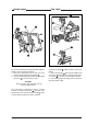

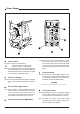
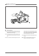
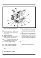
Table Of Contents
- Contents
- About this Manual
- Introduction
- Technology
- Smart Card
- Features
- Important Precautions
- Assembling the Units
- Transport Case
- Lens
- 1.5-inch Viewfinder
- 1.5-inch Viewfinder Accessories
- Other Viewfinders
- Zoom Controls
- Microphone
- Tripod Adapter Plate
- SuperXPander
- Shoulder Pad
- Rain and Off-use Cover
- Script board
- Top Light
- Configurations
- Basic Configurations
- Location of Controls and Functions
- Power Supply
- Security and Access
- Video Functions
- Monitoring Functions
- Viewfinder
- Viewfinder Indicators
- Audio
- Intercom
- Control Functions
- Auxilary Functions
- Shooting
- Using the Camera
- Standard settings
- Colour Bar
- Gain selection
- Optical filter selection
- Colour temperature selection
- Auto-White Balance
- Shooting Screens
- Exposure Time
- Using the Menu System
- Introduction
- Systems Menu
- Appendix
- System Menu Structure
- List of System Menu Functions
- List of Abbreviations
- Introduction
- Assembling the Units
- Configurations
- Location of Controls
- Shooting
- Using the Menu System
- Appendix

Assembling the Units Operator’s Manual LDK 200 Triax 2-11
C
le
a
r
C
le
a
r
A
1
S
ta
r
4P N
D
1
/4
B
1
S
ta
r 6
P
N
D
1
/1
6
C
1
S
o
ft f
o
cu
s
N
D
1
/6
4
D
1
Script board
To mount the optional Script board (LDK 6985/21)
onto the camera proceed as follows:
a. Secure the Script board to the top-rear of the
camera with the quick mount adapter
1
.
b. Connect Script board light cable to the script light
connector
2
at the rear of the camera.
CAUTION
Ensure that the script light does not use
more than 3W of power.
The script light is switched on and off, and the
intensity is varied with the knob
3
at the rear of the
Script board. The retaining rings and clip
4
can be
screwed onto the right or left side if required.
Clear
Clear
A
1
Star 4P N
D1/4
B2
Star 6P
ND 1/1
6
C
3
Soft focus
ND 1/6
4
D
4
Top Light
To mount a top light
1
onto the camera, proceed as
follows:
a. Screw the top light
1
into either the WW1/4”-20
screw hole
2
located on the carrying handle or the
screw hole
3
on the top of the microphone holder.
b. Power the top light according to the instructions
delivered with the light.
Cl
ar
Clear
A
1
1
1
1
2
2
3
3
4