LDK 20(S) Studio Camera Technical Manual 3922 496 48591 St.
Declaration of Conformity We, Thomson Broadcast Solutions Nederland B.V., Kapittelweg 10, 4827 HG Breda, The Netherlands declare under our sole responsibility that this product is in compliance with the following standards: : Safety EN60065 EN55103-1 : EMC (Emission) EN55103-2 : EMC (Immunity) following the provisions of: a. the Safety Directives 73/23//EEC and 93/68/EEC b.
LDK 20(S) Studio Camera Technical Manual Contents About This Manual ................................................ II Safety Instructions ........................................... 1-1 Safety Summary ................................................ 1-2 Cautions and Warnings ...................................... 1-2 Earthing ............................................................. 1-3 Installation ........................................................ 2-1 Packing/Unpacking .......................
About This Manual Service policy The LDK 20(S) is a sophisticated camera containing state-of-the-art electronic components which are designed to provide long-life operation without the need for maintenance. With this in mind, the service policy of Thomson Multimedia Broadcast Solutions endeavours to ensure that help will be quickly on hand in the unlikely event of anything going wrong.
Section 1 Safety Instructions This section outlines the precautions that must be taken into account when using the LDK 20(S) Studio Camera. Contents Safety Summary ........................................................ 1-2 Cautions and Warnings ............................................. 1-2 Safety Instructions Earthing .....................................................................
Safety Summary Cautions and Warnings This informaton is intended as a guide for trained and qualified personnel who are aware of the dangers involved in handling potentially hazardous electrical/electronic equipment. It is not intended to contain a complete list of all safety precautions which should be observed by personnel in using this or other electronic equipment. When performing service, be sure to read and comply with the warning and caution notices appearing in the manuals.
Earthing Symbol Colour Red The rear of a CPU has two separate screw terminals for protective earth (PE) and video earth (VE). Explanation High voltage terminal at which a voltage, with respect to an other terminal, exists or may be adjusted to 1000V or more. VE Metal strap PE Yellow/Black Live part.
1-4 Technical Manual LDK 20(S) - Studio Camera Safety Instructions
Section 2 Installation This section provides information which is relevant when the camera is to be used for the first time. Packing and unpacking instructions together with information on the integration of the camera into your studio system are provided. The procedures for the customization of certain hardware functions and connector information is also provided. Contents Packing/Unpacking ............................................ 2-2 Local / Remote Power Supply ............................
Packing/Unpacking Inspect the shipping container for evidence of damage immediately after receipt. If the shipping container or cushioning material is damaged, it should be kept until the contents of the shipment have been checked for completeness and the units have been checked mechanically and electrically. The shipping container should be placed upright and opened from the top. Remove the cushioning material and lift out the contents.
Hardware Setup and Customization The camera is delivered in a ready-to-use state, however, there are occasions when it might be necessary to re-adjust some functions after, for example, fitting a new lens. A large number of functions can be set-up using the control facilities of the menu system. In addition to this software set-up there are some functions which can be selected or adjusted internally in the camera. Refer to the next chapters for instructions.
Test Sawtooth Lens matching A test sawtooth signal is normally only used for adjustment procedures. Jumper X3 on Video processor 1 board provides a choice between two internal signals or an external signal. Internal signals Set jumper X3 to position BC to get the nominal sawtooth. This is used for checking amplitudes. Set jumper X3 to position AB to get a small sawtooth (approximately 25% nom.). This small sawtooth is used for checking painting or colour temperature ranges.
Analogue Ch1-Ch2 Dipswitch Settings Two analogue channels (AN 0 and AN 1) are available from the base station to the camera via the triax cable and can be used to transmit L.F. signals. For example, joystick control or pan and tilt. The input signals are applied to the Auxiliary connector of the base station. The output signals are available on the Auxiliary connector of the camera. The input signal and output signal voltage is between 0 and 5Vdc.
Viewfinder Cadre Indication Cadre On/Off Switch S6 on the Sync./shading board allows the cadre in the viewfinder to be switched on permanently or to be controlled by the menu system. Position AB selects (remote-) menu control (factory setting); position AC switches the cadre on permanently. If S6 is in the remote position then you can select in Menu VF/Lens Cadre On or Off. The cadre is switched to the 4:3 format or to the 16:9 format depending on the position of the aspect ratio switch.
Audio / Intercom settings Audio microphone signals The high-pass filters in the audio channels reduce the background noise in the audio microphone signals.
Private Data Private data channels can be used for the transmission of serial data via the triax cable. For example, electronic scriptboard or character data for a video display unit can be transmitted to the camera. To select the function of the camera to base station channel use S802 on the Audio/intercom board. Position AB selects the tracker microphone function (factory setting); position AC selects the private data function.
Connectors and Cables VTR connector 24 22 17 11 23 6 18 12 7 1 B A 26-pin male; panel view part number 3922 040 02551 A. B. 1. 2. 3. 4. 5. 6. 7. 8. 9. 10. 11. 12. 13. 14. 15. 16. 17. 18. 19. 20. 21. 22. 23. 24. + Battery from VTR (10.7 to 17V) Ground CVBS (only available with encoder option present) CVBS Return (only available with encoder option present) Y + S Return Y + S (luminance + sync.
Viewfinder connector 9 1 15 8 1. 2. 3. 4. 5. 6. 7. 8. 9. 10. 11. 12. 13. 14. 15.
Camera headset connector 1 6 2 5 3 1. 2. 3. 4. 5. 6. Telephone left Not connected Microphone Microphone return Telephone right Telephone return 1. 2. 3. 4. 5.
Auxiliary connector 10 11 3 9 4 2 8 5 7 6 1. 2. 3. 4. 5. 6. 7. 8. 9. 10. 11. +5VL 0VL AN0 AN1 Spare Not connected Private Data Camera - Base Station Ground Private Data Base Station - Camera Ground Shield 1 Fischer 11-pin female; panel view part number 3922 040 02512 Tracker communication connector 10 11 3 9 4 2 8 5 7 1. 2. 3. 4. 5. 6. 7. 8. 9.
Script light connector 1 1. +12V (Maximum Dissipation 3W) 2. Power Return 3.
Specifications LDK20 Camera system Transmission system NTSC/PAL Pick-up device 3 x 2/3-inch Thomson DPM Frame Transfer CCDs Smear performance No vertical smear Aspect ratio 4:3/ 16:9 switchable Picture elements 4:3 and 16:9 aspect ratio NTSC: 1000(h) x 498(v) PAL: 1000(h) x 594(v) Optical system F1.4 with quartz filter Filter cassette with Optical filters Exchangeable filter cassette with remote selectable 6 positions: Clear; ND 0.6; ND 1.2; ND 1.
Section 3 Replacements This section gives information on the procedures to follow when replacing printed circuit boards and mechanical components at first line level. Contents Introduction ........................................................ 3-2 Printed circuit boards ......................................... 3-2 Front module ...................................................... 3-3 Replacements Filterwheel Cassette ........................................... 3-4 Power supply ......................
Introduction Printed circuit boards The instructions given in this section are restricted to those modules which can be replaced at the first line level. After a printed circuit board has been replaced it is sometimes necessary to carry out adjustments to match the new boards to your camera and so maintain the performance levels. The relevant adjustment procedures are referenced in section 4. The procedures for removing the modules should be followed in reverse order when remounting the units.
Front module 1 1 2 2 2 2 1 1 To remove the front module proceed as follows: a. On the frontside of the camera remove the four screws 1 securing the front assembly. b. Remove the front assembly from the camera. c. Remove the Front Interconnection Board by unscrewing two screws from the backside of the front module. d. Loosen the four screws 2 securing the front module. e. Slide the front module straight out of the front assembly.
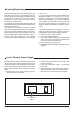
Filterwheel Cassette Power supply 1 2 1 2 On Air Power light Sys/Iso VTR Remote Camera install View finder Intercom Audio Function A Function B Function C Function D Filter 1 Filter 2 Filter 3 Filter 4 Auto white R Ext.1 G Ext.2 B Y/Ext. Select 1 Script light Filter 5 Filter 6 Progr -G Prod Call Eng On Off PTT 12V 0.25A To remove the filterwheel cassette proceed as follows: a. Loosen the two screws 1 securing the cover to the body of the front assembly. b.
Section 4 Adjustments This section contains the adjustment procedures to be followed to obtain the best performance from the camera. These procedures need only be used if, following a module replacement, the camera does not perform according to specifications. Contents Introduction .......................................................... 4-2 Test Equipment ................................................... 4-3 Set-up Instructions ...............................................
Introduction This camera is factory tested and adjusted for operational use. Under normal circumstances, the internal potentiometers do not need to be adjusted. If it is discovered that the camera is misaligned, the following procedures are given as a guide for competent service personnel, who have a thorough knowledge of the camera and have the use of calibrated equipment, to realign the camera. The camera head adjustment procedures are designed as separate units.
Test Equipment Set-up Instructions The following is a list of equipment required to carry out the adjustment procedure: • Set of board extenders LDK 4830/21 • Oscilloscope (with cursor measurement) • Spotlight 3200K • Gamma Test chart 4:3 / 16:9 • Waveform monitor • Colour monitor • Multimeter • Master Control Panel LDK 4607 / LDK 4609 • Operational Control Panel LDK 4624 / LDK 4628 / LDK 4629 • Audio Analyser • Base Station LDK 4053 Before carrying out any adjustments the following steps are recommended
Extender Board B A B A 24 22 20 18 16 14 12 10 8 6 23 21 19 17 15 13 11 9 7 5 S24 S22 S20 S18 S16 S14 S12 S10 S8 S6 S23 S21 S19 S17 S15 S13 S11 S9 S7 S5 4 3 S4 S3 S2 S1 2 1 23 24 1 2 2 1 B - CONNECTOR MP MP MP MP B A B A 1 2 S1 S2 3 4 S3 S4 5 7 9 11 13 15 17 19 21 23 6 8 10 12 14 16 18 20 22 24 S5 S7 S9 S11 S13 S15 S17 S19 S21 S23 S6 S8 S10 S12 S14 S16 S18 S20 S22 S24 A - CONNECTOR 24 23 TOP SIDE 4-4 Technical Manual LDK 20(S) - Studio Camera Adjustments
Video Processor 1 Board Setting-up the Camera Note: Video Processor 1 must be adjusted in combination with the Sync./Shading board. 1. For local powering of the camera in the stand-alone mode (see User Guide, Section 4). 2. Recall Factory Standard File on MCP or OCP. On MCP set: OPERATE MENU Knee : Off Contour : Off Gamma : Lin. Blk. Str. : Off Auto Iris : Off SETUP 1 MENU Studio mode: Off Flare : Off White clip : Off SETUP 2 MENU Soft cont. : Off SETUP 3 MENU Skin cont.
Video Processor 1 Board VP1 VP 1 Black offset B ZR208 ZR606 ZR614 ZR611 Dummy offset B Saw Ampl B MP611 offset B ZR206 ZR214 ZR211 23 24 Black offset R ZR408 Dummy offset R Saw Ampl R MP offset R 211 X55 ZR406 ZR414 ZR411 ZR608 MP620 MP610 MP630 MP220 MP210 MP230 MP420 MP410 Dummy offset G Black offset G MP430 Ampl G Saw offset G MP411 G 6 R - 12 G - 12 6 R B - 15 1 2 2 1 MP41 MP0 2 1 Test X4 MP40 MP80 ZR111 Ampl Test B X3 A C Test MP240 MP90 G-8 MP44 MP640 X56 MP110 MP100
Video Processor 1 Board Black Offset 6. In the Install/Gain menu set the gain for + to 12dB and for ++ to 30dB (the standard values are 6dB and 12dB). 7. While switching between 0dB gain and 30dB gain, adjust black level during the active line to the same as the clamp level.
Video Processor 1 Board VP1 VP 1 Black offset B ZR208 ZR614 ZR611 Dummy offset B Saw Ampl B MP611 offset B ZR206 ZR214 ZR211 23 24 Black offset R ZR408 Dummy offset R Saw Ampl R MP offset R 211 X55 ZR406 ZR414 ZR411 ZR608 MP620 MP610 MP630 MP220 MP210 MP230 MP420 ZR606 MP410 Dummy offset G Black offset G MP430 Ampl G Saw offset G MP411 G-6 R - 12 B - 15 1 2 2 1 MP41 MP0 Test 2 1 X4 MP40 MP80 B X3 A C Test Ampl Test Shift R112 Slope Test R108 Shift Test TOP SIDE 4-8 MP240
Video Processor 1 Board Test Sawtooth Nominal Settings 15. Sawtooth amplitude Measure at: Adjust with: Required result: MP110 ZR111 -1000mV Correct: 10µS 0.2V 100 90 10 0% VA+1.00V 16. Sawtooth slope Set sawtooth amplitude to 100% on oscilloscope, measure between 10% and 90% and adjust slope test. Measure at: Adjust with: Required result: MP110 R112 25 µS Correct: 5µS 0.2V 100 90% 90 10% 10 0% t+25.0µS 25µS 17. Sawtooth horizontal shift Set master black level to +10%.
Digital Video Processor ZR725 Black off set limiter sharp B ZR741 MP700 23 24 MP300 G - 11 R - 21 ZR325 Black off set limiter sharp R ZR341 X51 B - 22 ZR541 ZR525 Black off set limiter sharp G MP500 1 2 ZR830 Black off set limiter sharp Y ZR841 MP840 2 1 ZR432 Amplitude Black G X52 24 23 BOTTOM SIDE 4-10 Digital Video Processing MP430 ZR232 Amplitude Black R MP230 ZR632 Amplitude Black B MP630 3922 406 84950 Technical Manual LDK 20(S) - Studio Camera Adjustments
Digital Video Processor 1. Place Digital Video Processor on service extender. Set master black level to 50. Check that individual R, G and B black levels are set to 50. Switch off test sawtooth. Black Offset Level 2. Switch on colour bar. 3. Adjust black offset during the active line to the same as the clamp level. Measure at: Adjust with: Required result: X51-21 (R) ZR325 (R) 0mV (R) Correct: 10µS 0.2V 100 90 Clamp level 10 0% VA+1.
ZR271 ZR471 ZR671 Digital Video Processor Subboard Subboard DSP BOTTOM SIDE 3922 406 84960 Digital Video Processor ZR725 Black off set limiter sharp B ZR741 MP700 23 24 MP300 G - 11 R - 21 ZR325 Black off set limiter sharp R ZR341 X51 B - 22 ZR541 ZR525 Black off set limiter sharp G MP500 1 2 ZR830 Black off set limiter sharp Y ZR841 MP840 2 1 ZR432 Amplitude Black G X52 24 23 BOTTOM SIDE 4-12 Digital Video Processing MP430 ZR232 Amplitude Black R MP230 ZR632 Amplitude Black B
Digital Video Processor Subboard Gain DAC. 1. Adjust bar output amplitude. PAL Measure at: Adjust with: Required result: X51-21 ZR271 (R) +1400mV (R) Correct: 10µS 0.2V 100 90 1400 mV 10 0% VA+1.40V Measure at: Adjust with: Required result: X51-11 ZR471 (G) +1400mV (G) Correct: 10µS 0.2V 100 90 1400 mV 10 0% VA+1.40V Measure at: Adjust with: Required result: X51-22 R671 (B) +1400mV (B) Correct: 10µS 0.2V 100 90 1400 mV 10 0% VA+1.
Digital Video Processor ZR725 Black off set limiter sharp B ZR741 MP700 23 24 MP300 G - 11 R - 21 ZR325 Black off set limiter sharp R ZR341 X51 B - 22 ZR541 ZR525 Black off set limiter sharp G MP500 1 2 ZR830 Black off set limiter sharp Y ZR841 MP840 2 1 ZR432 Amplitude Black G MP430 X52 Y - 24 24 23 BOTTOM SIDE 4-14 Digital Video Processing ZR232 Amplitude Black R MP230 ZR632 Amplitude Black B MP630 3922 406 84950 Technical Manual LDK 20(S) - Studio Camera Adjustments
Digital Video Processor Gain Video 1. Place Digital Video Processor on service extender. 2. Switch off colour bar and Test sawtooth on. 3. Adjust white output amplitude. Measure at: Adjust with: Required result: X51-21 (R) ZR232 (R) +1400mV (R) X51-11 (G) ZR432 (G) +1400mV (G) X51-22 (B) ZR632 (B) +1400mV (B) Correct: 10µS 0.5V 100 90 10 0% VA+1.40V White limiter 4. Set gain to +6dB. In setup 1 menu set white clip on. Set individual white limiter to: Master G = 60, R = 60, B = 60. 5.
Video Miscellaneous Board Video Video Misc Misc ZR247 Cadre Contrast ZR94 B-Y Level ZR600 ZR601 Wh. Pulse BMux Ampl. Gain BMux 36 ZR93 R-Y Level ZR91 ZR111 White White Pulse GMux Ampl. Balance Gain GMux Mon.Video Level MP6 R/G/B/Y/VFCNT MP5 ZR85 ZR92 MP7 White Pulse Sync. RMux Ampl. Composite MP0 Ampl.
Video Miscellaneous Board 1. Place Video Miscellaneous Board on service extender. VF sync. oscillator 2. Test sawtooth off. 3. Adjust VF sync. frequency. Measure at: Adjust with: Required result: MP2 ZL4 +2.5V DC level Output amplitude 4. Test sawtooth on. 5. Adjust Y output amplitude. Measure at: Adjust with: Required result: X17A-11 ZR92 +1400mV PAL +1428mV NTSC PAL NTSC 10µS 0.2V 10µS 0.2V 100 100 90 90 10 10 0% 0% VA+1428mV VA+1400mV 6. Adjust Y sync. output amplitude.
Video Miscellaneous Board Video Video Misc Misc ZR247 Cadre Contrast ZR94 B-Y Level ZR600 ZR601 ZR200 ZR201 Wh. Pulse BMux Ampl. Gain BMux 36 ZR93 R-Y Level ZR91 ZR111 White White Pulse GMux Ampl. Balance Gain GMux Mon.Video Level MP6 R/G/B/Y/VFCNT MP5 ZR85 ZR92 MP7 White Pulse Sync. RMux Ampl. MP0 Composite Ampl.
Video Miscellaneous Board R-Y amplitude 10. Adjust R-Y output amplitude. Measure at: Adjust with: Required result: X17A-10 ZR93 1400mV Correct: 10µS 0.2V 100 90 10 0% VA+1400mV B-Y amplitude 11. Adjust B-Y output amplitude. Measure at: Adjust with: Required result: X17A-16 ZR94 1400mV Correct: 0.2V 10µS 100 90 10 0% VA+1400mV Video Mux output 12. Colour bar off. 13. Test sawtooth on. 14. Adjust R-Mux output.
Video Miscellaneous Board Video Video Misc Misc ZR247 Cadre Contrast ZR94 B-Y Level ZR600 ZR601 Wh. Pulse BMux Ampl. Gain BMux 36 ZR93 R-Y Level ZR91 ZR111 White White Pulse GMux Ampl. Balance Gain GMux Mon.Video Level MP6 R/G/B/Y/VFCNT MP5 ZR85 ZR92 MP7 White Pulse Sync. RMux Ampl. MP0 Composite Ampl.
Video Miscellaneous Board White pulse amplitude 17. Connect camera to a base station and switch to Triax mode. 18. Adjust the white pulse in line 10 (PAL), in line 13 (NTSC) for the R-Mux output. Measure at: Adjust with: Required result: X17A-27 ZR201 700mV Correct: 100 90 10 0% 19. Adjust the white pulse in line 10 (PAL), in line 13 (NTSC) for the G-Mux output. Measure at: Adjust with: Required result: X17A-19 ZR401 700mV Correct: 100 90 10 0% 20.
Video Miscellaneous Board Video Misc Misc ZR247 Cadre Contrast ZR94 B-Y Level Gain BMux Wh. Pulse BMux Ampl. 36 ZR93 R-Y Level ZR91 White Balance ZR400 Gain GMux ZR401 White Pulse GMux Ampl. ZR201 Mon.Video Level MP6 R/G/B/Y/VFCNT MP5 ZR85 Gain RMux MP0 White Pulse RMux Ampl. ZR200 ZR111 ZR92 Sync. Ampl.
Video Miscellaneous Board Black indicator level 25. Use the controls at the rear of the camera to set the white indicator level for the monitoring output by navigating through the menu system to menu number 318 and setting the value to 85. 26. Connect oscilloscope terminated with 75 Ohm to the VF output of the camera. 27. Adjust the black level of the indicators of the VF output signal to the same level as the blanking.
Video Miscellaneous Board Video Video Misc Misc ZR247 Cadre Contrast ZR94 B-Y Level ZR600 ZR601 Wh. Pulse BMux Ampl. Gain BMux 36 ZR93 R-Y Level ZR91 ZR111 White White Pulse GMux Ampl. Balance Gain GMux Mon.Video Level MP6 R/G/B/Y/VFCNT MP5 ZR85 ZR92 MP7 White Pulse Sync. RMux Ampl. MP0 Composite Ampl.
Video Miscellaneous Board Zoom bar 29. Mount lens on camera. 30. Test sawtooth off and set filter to clear. 31. Open iris for nominal video. 32. Set potentiometers ZR90 and ZR283 to their mid-position. 33. Set lens to the wide angle position and adjust the start zoom bar potentiometer ZR90 so that there is just a small gap in the zoom bar at the left side of the viewfinder display. Measure at: Adjust with: VF display ZR90 Required result: Correct: 34.
Sync./Shading Board Sync Shad ZR236 ZR137 ZR263 ZR710 ZR463 ZR92 ZR663 ZR73 ZR237 23 24 ZR238 MP703 ZR239 MP217 MP704 ZR265 MP209 X61 MP10 MP705 ZR266 MP11 ZR436 MP13 MP9 MP12 MP0 ZR437 1 2 2 1 654321 ZR438 S1 MP417 MP409 ZR439 ZR465 ZR466 ZR636 X62 ZR637 ZR700 ZR638 ZR639 MP609 ZR665 MP707 24 23 MP706 ZR666 ZR300 MP1 Sync.
Sync./Shading Board Setting-up Note: Sync./Shading board must be adjusted in combination with Video Processor 1 Board. 1. Put Sync./Shading Board on a service extender. 2. Put Video Processor 1 Board on a service extender and remove jumpers 7, 9, 11, 13, 17 and 19 from connector B of the service extender to interrupt the input from the front and jumpers 6, 12 and 15 to interrupt the black shading correction. 3.
Sync./Shading Board Sync Shad ZR236 ZR137 ZR263 ZR710 ZR463 ZR92 ZR663 ZR73 ZR237 23 24 ZR238 MP703 ZR239 MP217 MP704 ZR265 MP209 X61 MP10 MP705 ZR266 MP11 ZR436 MP13 MP9 MP12 MP0 ZR437 1 2 2 1 654321 ZR438 S1 MP417 MP409 ZR439 ZR465 ZR466 ZR636 X62 ZR637 ZR700 ZR638 ZR639 MP609 ZR665 MP707 24 23 MP706 ZR666 ZR300 MP1 Sync.
Sync./Shading Board 8. On connector B of the service extender remove the short circuits on the input to Video Processor 1 Board by disconnecting the jumpers from B7 to B9, B11 to B13 and B17 to B19, Reconnect A6 to B6 A7 to B7 A9 to B9 A11 to B11 A12 to B12 A13 to B13 A15 to B15 A17 to B17 A19 to B19 on connector B of the service extender. Dummy offset adjustment 9. On Video Processor 1 Board adjust video level equal to blanking DC level.
Sync./Shading Board Sync Shad ZR236 ZR137 ZR263 ZR710 ZR463 ZR92 ZR663 ZR73 ZR237 23 24 ZR238 MP703 ZR239 MP217 MP704 ZR265 MP209 X61 MP10 MP705 ZR266 MP11 ZR436 MP13 MP9 MP12 MP0 ZR437 1 2 2 1 654321 ZR438 S1 MP417 MP409 ZR439 ZR465 ZR466 ZR636 X62 ZR637 ZR700 ZR638 ZR639 MP609 ZR665 MP707 24 23 MP706 ZR666 ZR300 MP1 Sync.
Sync./Shading Board Edge clip level 16. Set edge clip level potentiometers in their mid-position. Measure at: Adjust with: Required result: VF out R ZR237 Mid-position VF out G ZR437 Mid-position VF out B ZR637 Mid-position Edge gain correction 17. On MCP set: OPERATE MENU Gain : ++ Exposure : Nom. 18. Adjust the parabola correction potentiometers. Measure at: Adjust with: Required result: VF out R ZR239 Flat shading signal VF out G ZR439 VF out B ZR639 19.
Sync./Shading Board Sync Shad ZR236 ZR137 ZR263 ZR710 ZR463 ZR92 ZR663 ZR73 ZR237 23 24 ZR238 MP703 ZR239 MP217 MP704 ZR265 MP209 X61 MP10 MP705 ZR266 MP11 ZR436 MP13 MP9 MP12 MP0 ZR437 1 2 2 1 654321 ZR438 S1 MP417 MP409 ZR439 ZR465 ZR466 ZR636 X62 ZR637 ZR700 ZR638 ZR639 MP609 ZR665 MP707 24 23 MP706 ZR666 ZR300 MP1 Sync.
Sync/Shading Board 24. On Video Processor 1 Board adjust the vertical sawtooth potentiometer for no sawtooth information. (Select the viewfinder R, G and B output signals in the VF/Lens - VF Inst menu.) Measure at: Adjust with: Required result: VF out R ZR214 Video signal as flat VF out G ZR414 as possible in VF out B ZR614 vertical direction. Video Processor 1 Board Black Offset 25. In the Install/Gain menu set the gain for + to 12dB and for Max gain (the standard values are 6dB and 12dB). 26.
Video Miscellaneous Board Video Misc Misc ZR247 Cadre Contrast ZR94 B-Y Level ZR600 ZR601 Wh. Pulse BMux Ampl. Gain BMux 36 ZR93 R-Y Level ZR91 ZR111 White White Pulse GMux Ampl. Balance Gain GMux Mon.Video Level MP6 R/G/B/Y/VFCNT MP5 ZR85 ZR92 MP7 White Pulse Sync. RMux Ampl. MP0 Composite Ampl.
Video Miscellaneous Board Auto iris 1. Point camera at and fill frame with a white 90% reflecting test chart, illuminated with a 3200K spotlight. Set iris to F5.6. Measure at: Adjust with: CVBS out Required result: Waveform monitor 100% video level. 2. On OCP, ensure that the IRIS CENTRE control is turned fully counterclockwise and the IRIS RANGE control is turned fully clockwise. Move iris control first fully up and then fully down. Then set iris control to its midposition. 3.
Encoder Board PAL Encoder Encoder R4 MP14 Chroma Chroma CVBS CVBS MP7 R14 ZR202 B-Y Gain ZR203 Q Balance ZR205 R-Y Gain ZR206 I Balance ZR211 Burst Phase MP12 ZR210 Burst MP8 36 ZR209 Burst MP6 MP17 MP13 MP11 MP19 ZR215 Lock Range ZR216 Osc.
Encoder Board PAL Set-up 1. Switch off power. Place encoder board on service extender. Genlock camera with black burst signal. Switch on power. 2. Connect oscilloscope via a vectorscope terminated with 75Ohm to the CVBS output of the camera. 3. Switch on colour bar. Black balance 4. Turn chroma potentiometer R4 on encoder board fully clockwise (max. chroma). 5. Adjust the I and Q balance potentiometers for minimum unbalance in black.
Encoder Board PAL Encoder Encoder R4 MP14 Chroma Chroma Chroma CVBS CVBS MP7 R14 ZR202 B-Y Gain ZR203 Q Balance ZR205 R-Y Gain ZR206 I Balance ZR211 Burst Phase MP12 ZR210 Burst MP8 36 ZR209 Burst MP6 MP17 MP13 MP11 MP19 ZR215 Lock Range ZR216 Osc.
Encoder Board PAL B-Y amplitude 11. On the encoder board disconnect MP7 from ground and connect MP8 to ground. 12. Adjust with the B-Y gain potentiometer until the colour vector dots correspond with the indication marks on the U-axis of the graticule. Measure at: Adjust with: CVBS out ZR202 Required result: Correct: % VOLT 120 cy R 100 g V 75 100 60 40 20 0.7 MG 80 YL b 5 B -5 U yl 0 0 20 mg G r 43 CY 0.3 13. Disconnect MP8 from ground. R-Y / B-Y phase 14.
Encoder Board PAL Encoder Encoder R4 MP14 Chroma Chroma CVBS CVBS MP7 R14 ZR202 B-Y Gain ZR203 Q Balance ZR205 R-Y Gain ZR206 I Balance ZR211 Burst Phase MP12 ZR210 Burst MP8 36 ZR209 Burst MP6 MP17 MP13 MP11 MP19 ZR215 Lock Range ZR216 Osc.
Encoder Board PAL Burst amplitude 19. Adjust the burst amplitude potentiometer to obtain a burst amplitude of 300mV. Measure at: Adjust with: Required result: CVBS out ZR210 300mV Correct: 2µS 0.1V 100 90 10 0% VA+300mV Burst timing 20. Observe waveform monitor or oscilloscope and adjust the burst position so that it is 5.6µS from the leading edge of the line synchronisation. Measure at: Adjust with: CVBS out ZR209 Required result: Correct: 1µS 50mV 100 90 10 0% t+5.
Encoder Board NTSC R4 Chroma MP14 ZR203 Q Balance MP7 ZR202 B-Y Gain Chroma ZR205 R-Y Gain CVBS CVBS R14 ZR211 Burst Phase MP12 I Balance ZR210 Burst MP8 ZR212 Bar Width ZR201 Q Amplitude ZR206 36 ZR207 I Amplitude ZR209 Burst MP6 X11A Encoder MP17 MP13 MP11 ZR213 White Bar MP9 Ampl. MP19 ZR215 Lock Range ZR216 Osc.
Encoder Board NTSC Set-up 1. Switch off power. Place encoder board on service extender. Genlock camera with black burst signal. Switch on power. 2. Connect oscilloscope via a vectorscope terminated with 75Ohm to the CVBS output of the camera. 3. Switch on colour bar. Black balance 4. Turn chroma potentiometer R4 on encoder board fully clockwise (max. chroma). 5. Adjust the I and Q balance potentiometers for minimum unbalance in black.
Encoder Board NTSC R4 MP14 Chroma Chroma CVBS CVBS ZR203 Q Balance MP7 ZR202 B-Y Gain ZR205 R-Y Gain R14 ZR211 Burst Phase MP12 I Balance ZR210 Burst MP8 ZR212 Bar Width ZR201 Q Amplitude ZR206 ZR207 I Amplitude 36 ZR209 Burst MP6 X11A Encoder Encoder MP17 MP13 MP11 ZR213 White Bar MP9 Ampl. MP19 ZR215 Lock Range ZR216 Osc.
Encoder Board NTSC I amplitude 9. Set I gain potentiometer ZR205 in its mid-position. 10. Connect MP7 on the encoder board to ground. 11. Adjust with the chroma potentiometer until the colour vector dots correspond with the indication marks on the I-axis of the graticule. Measure at: Adjust with: CVBS out R4 Required result: Correct: IRE 0% 120 100 12.5% R I 80 MG 60 40 Q 5 YL 75 100 0 B 20 -5 75% G 20 CY 40 100% Q amplitude 12.
Encoder Board NTSC R4 MP14 Chroma Chroma CVBS CVBS ZR203 Q Balance MP7 ZR202 B-Y Gain ZR205 R-Y Gain R14 ZR211 Burst Phase MP12 I Balance ZR210 Burst MP8 ZR212 Bar Width ZR201 Q Amplitude ZR206 36 ZR207 I Amplitude ZR209 Burst MP6 X11A Encoder Encoder MP17 MP13 MP11 ZR213 White Bar MP9 Ampl. MP19 ZR215 Lock Range ZR216 Osc.
Encoder Board NTSC I / Q 90° phase 16. Connect MP7 on the encoder board to ground. 17. With the phase potentiometer on the vectorscope, place the I vectors along the I-axis of the graticule. Measure at: Adjust with: Required result: Correct: IRE 0% 120 100 12.5% R I 80 MG 60 40 Q 5 YL 75 100 0 B 20 -5 75% G 20 CY 40 100% 18. On the encoder board disconnect MP7 from ground and connect MP8 to ground. 19.
Encoder Board NTSC R4 MP14 Chroma Chroma CVBS CVBS ZR203 Q Balance MP7 ZR202 B-Y Gain ZR205 R-Y Gain R14 ZR211 Burst Phase MP12 I Balance ZR210 Burst MP8 ZR212 Bar Width ZR201 Q Amplitude ZR206 ZR207 I Amplitude 36 ZR209 Burst MP6 X11A Encoder Encoder MP17 MP13 MP11 ZR213 White Bar MP9 Ampl. MP19 ZR215 Lock Range ZR216 Osc.
Encoder Board NTSC Burst timing 23. Observe waveform monitor or oscilloscope and adjust the burst position so that it is 5.3µS from the leading edge of the line synchronisation. Measure at: Adjust with: Required result: CVBS out ZR209 5.3µS Correct: 1µS 50mV 100 90 10 0% t+5.3µs 178kHz 5.3µs Genlock free-running preset 24. Remove genlock signal from camera. 25. Turn lock range potentiometer ZR215 fully counterclockwise. 26.
Audio/Intercom LF Board ZMP0 ZMP200 S200 ZR260 Audio 2 Limiter Level S100 ZR160 Audio 1 Limiter Level Audio Int LF E D C ZMP100 E D C B ZMP340 A B A C S300 ZR360 Cam-Mic ZR310 Cam-Mic Limiter Preset Level Level ZR460 Tracker Limiter Level 1 ZR410 Tracker Preset Level S740 ZMP700 ZMP701 ZR820 ZMP620 Side Tone Preset ZMP601 Level ZMP521 ZMP500 TOP SIDE 4-50 2 S200 Audio 2 Phantom Power B1-C1/B2-C2: GND A1-B1/A2-B2: +48V D1-E1/D2-E2: +12V Camera Menu Audio 2 High Pass Filter 40dB 0dB S10
Audio/Intercom LF Board Set-up 1. Set up camera in triax mode. Switch off power. Place audio/intercom LF board on service extender. Switch on power. Audio 1 level 2. Select an audio 1 level of -64dBu. 3. Apply a 1kHz test signal at -64dBu symmetrical to the audio 1 input of the camera 4. Adjust the audio preset potentiometer for a 1kHz signal at -12dBu on the audio 1 output pin. Measure at: Adjust with: Required result: X19A-35 ZR110 -12dBu Audio 1 limiter 5.
Audio/Intercom LF Board ZMP0 ZR360 Cam-Mic ZR310 Limiter Cam-Mic Preset Level Level ZR460 Tracker Limiter Level 1 ZR410 Tracker Preset Level S470 ZMP701 ZR820 ZMP620 Side Tone Preset ZMP601 Level ZMP521 ZMP500 TOP SIDE 4-52 Camera Menu Tracker Mic. Gain 40dB 0dB S470 Signal Choice S450 Signal Choice S740 Signal Choice AB: Tracker Mic. AC: Private Data AB: Prog.
Audio/Intercom LF Board Cameraman intercom microphone 12. Apply a 1kHz test signal at -64dBu to the cam. intercom mic. input of Audio/Intercom LF Board (X19A-25). 13. Adjust the cam. mic. preset potentiometer for a 1kHz signal at -6dBu on the microphone output pin of the board. Measure at: Adjust with: Required result: X19B-10 ZR310 -6dBu Cameraman intercom microphone PL 14. Adjust the side tone potentiometer for a 1kHz signal at 0dBu on the telephone output pin.
Audio/Intercom LF Board ZMP0 ZR360 Cam-Mic ZR310 Limiter Cam-Mic Preset Level Level ZR460 Tracker Limiter Level 1 ZR410 Tracker Preset Level S470 ZMP701 ZR820 ZMP620 Side Tone Preset ZMP601 Level ZMP521 ZMP500 TOP SIDE 4-54 Camera Menu Tracker Mic. Gain 40dB 0dB S470 Signal Choice S450 Signal Choice S740 Signal Choice AB: Tracker Mic. AC: Private Data AB: Prog.
Audio/Intercom LF Board RTS MODE Cameraman intercom microphone PL 1. Apply a 1kHz test signal at -64dBu to the cam. intercom mic. input of Audio/Intercom LF Board (X19A-25). 2. Adjust the cam. mic. preset potentiometer for a 1kHz signal at -10dBu on the microphone output pin of the board. Measure at: Adjust with: Required result: X19B-13 ZR920 -10dBu Tracker intercom microphone PL 3. Apply a 1kHz test signal at -64dBu to the tracker intercom mic. input of Audio/Intercom LF board (X19A-13). 4.
ZR360 ZR340 ZR322 Gain G ZR160 ZR122 Gain R MP500 MP100 MP300 MP0 ZR522 Gain B ZR140 ZR540 ZR560 Pre Processor Board ZS500 TOP SIDE 4-56 ZS700 ZS100 Pre Processor Board 3922 406 83830 Technical Manual LDK 20(S) - Studio Camera Adjustments
Pre-Processor Board Gain Adjustment 1. Recall Factory Standard File on MCP or OCP. On MCP set: OPERATE MENU Knee : Off Auto Iris : Off Matrix sel. : 1:1 SETUP 1 MENU Wh. Limiter : Off Gamma : Lin. SETUP 4 MENU Asp. ratio : 4:3 2. Set the lighting conditions for 100% video output as follows: Colour temp. : 3200K Illumination : 2000lux Lens aperture : F8 Scene reflection : Reference white 90% (Minolta reference white tile) (2000 Lux with 90% reflectance is 573 cd/m2) 3.
4-58 Technical Manual LDK 20(S) - Studio Camera Adjustments
Section 5 Drawings This section contains block diagrams of the camera. The block diagrams are a useful help for tracing signals when fault finding. Contents Block Diagram Power Signals ............................ 5-2 Block Diagram Video Signals ............................. 5-3 Drawings Block Diagram Transmission Signals ................. 5-4 Block Diagram Control Signals ...........................
Block Diagram Power Signals +18V X23-16 -12Va X23-36 +V peltier X23-38 +13V +13V RET +5V GND -5V +3.3V X937-B16 +18V X937-B14 -12Va X937-Z22 +V peltier X23-39,40 X23-19,20 X23-14,34 X23-8,21,28,29 X23-15,35 X23X937-Z24 +5V data X937-Z26,B26 +13V X937-B28 +13V RET X180-1 +12V X180-2 +12V RET X937-Z20 +12V X937-B29 +5V X937-B20 +3.
Drawings Nam Video ZR606 B ZR406 G Technical Manual LDK 20(S) - Studio Camera R-X62-16 G-X62-14 B-X62-24 White Shading Sync./Shading R-X62-2 G-X62-5 B-X61-2 Black Shading X52-23 X52-9 X52-13 X51-17 X51-7 X51-23 X55-23 X51-10 View X55-5 X56-20 450mV X56-8 450mV X56-14 450mV R-X56-11 G-X56-9 B-X56-16 * Black Shading * V-Clamp * Preblanking * Gain Switch * Painting * Skin View * White Shading multiplier * Nam-Video (auto iris) R-X55-12 G-X55-6 B-X55-15 X55-19 55mV Bpp X55-17 Ret.
Block Diagram Transmission Signals SW.board Front X102A X107 3 7 TRIAX BACK PANEL Volume Prod Front X27-4 X24-9 VF.conn.
Block Diagram Control Signals DATA DATA N DATA BOARD X128-5 X128-6 X42-21 X42-14 G-GAIN X42-9 B-GAIN IRIS CONTROL X41-7 X41-5 DATA BS-CAM X41-13 DATA BS-CAM RET DATA CAM-BS X42-14 X42-16 DATA DATA N AN 0 AN 1 CONN PANEL RIGHT A-SDA B-SDA C-SDA E-SDA F-SDA H-SDA A-SCL B-SCL C-SCL E-SCL F-SCL H-SCL X140-29 X140-31 X231-12 X140-25 X140-33 X140-35 INTERCONN.
5-6 Technical Manual LDK 20(S) - Studio Camera Drawings