TCW710 digital BROADBAND WIRELESS CABLE MODEM
CAUTION CAUTION Disconnect power before To ensure reliable operation and to prevent servicing. overheating, provide adequate ventilation for this modem and keep it away from heat sources. Do not locate near heat registers or other heat-producing equipment. Provide for free air flow CAUTION around the Cable Modem and its power supply. This device is intended for indoor operation only. Telephone jacks Line 1 and Line 2 must not be connected to outside wiring.
Operating Information Operating Temperature:0˚ - 40˚ C (32˚ - 104˚ F) Storage Temperature: -30˚ to 65˚ C If you purchased this product at a retail outlet, please read the following: Product Information Keep your sales receipt to obtain warranty parts and service and for proof of purchase. Attach it here and record the serial and model numbers in case you need them. The numbers are located on the back of the product. Model No.
Important Information iv
Table of Contents Contents Chapter 1: Connections and Setup..................................................................................................................... 1 Introduction ...................................................................................................................... 1 Wireless Cable Gateway Features................................................................................. 1 What’s on the CD-ROM................................................................
Table of Contents Configuring Windows XP PCs ........................................................................................... 12 Connecting Your Devices................................................................................................. 13 Activating the Wireless Cable Gateway............................................................................. 13 Initialization..............................................................................................................
Table of Contents Status Web Page Group ................................................................................................... 32 Software Web Page.................................................................................................... 32 Connection Web Page................................................................................................ 33 Password Web Page...................................................................................................
Table of Contents Wireless Web Pages Group............................................................................................... 53 Performance ............................................................................................................. 53 Authentication .......................................................................................................... 53 Privacy .................................................................................................................
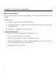
Chapter 1: Connections and Setup Chapter 1: Connections and Setup Introduction Wireless Cable Gateway Features Thank you for purchasing the TCW710 Wireless Cable Gateway. This device delivers the highest performance in data over cable technology. Ideal for home and small business users, this easyto-use communication device offers reliable connectivity as well as remarkable data transfer rates – up to 600 times faster than a 56K dial-up modem.
Chapter 1: Connections and Setup What’s on the CD-ROM If you connect a PC using the USB port on your gateway, you’ll need the USB drivers found on the CD-ROM. CD-ROM Contents: z Electronic copy of this user’s guide (.pdf format) z Adobe Acrobat Reader — application you can load to read .pdf format, if you don’t have it loaded already z USB drivers — required if connecting by USB Computer Requirements • USB 1.0 or 1.1 (PC only), Ethernet (10/100), 802.
Chapter 1: Connections and Setup Wireless Cable Gateway Overview Cable Internet Service Requirements • Cable company that offers EURO-DOCSIS-compliant Internet services What the Wireless Cable Gateway Does The Digital Wireless Cable Gateway serves as a two-way high-speed bridge between your personal computer and a cable Internet Service Provider (ISP).
Chapter 1: Connections and Setup Contact Your Local Cable Company You will need to contact your cable company to establish an Internet account before you can use your gateway. You should have the following information ready (which you will find on the sticker on the gateway): • The serial number • The model number • The Media Access Control (MAC) address Please verify the following with the cable company: • The cable service to your home supports EURO-DOCSIS-compliant two-way modem access.
Chapter 1: Connections and Setup System Overview The Wireless Cable Gateway is connected between your cable company and the PCs within your home, as pictured previously in the Wireless Cable Gateway Overview. The connection to the cable company is made by a coaxial cable, and is referred to as the WAN (Wide Area Network) side of your Wireless Cable Gateway. The connections to your PCs are made by your choice of several standard home networking methods: Ethernet, USB, or 802.
Chapter 1: Connections and Setup Understanding the Wireless Cable Gateway Connect Fig.
Chapter 1: Connections and Setup Your PC: Installing a PC Network Card If your PC does not already support Ethernet or USB, you must install a network interface card. Following is an example setup procedure: 1. Install an Ethernet card on your motherboard, following the card’s directions. 2. Power up your PC and follow the Add New Hardware Wizard’s instructions to install the driver. When asked to restart your computer at the end of the installation, click Yes. 3.
Chapter 1: Connections and Setup Your PC: Installing a TCP/IP Stack Follow these instructions to install the TCP/IP protocol stack on one of your PCs only after a network card has been successfully installed inside the PC. These instructions are for Windows Me. For TCP/IP setup under Windows NT, 2000, and XP, refer to your Windows documentation. 1. Click the Start button. Choose Settings and then Control Panel. 2. Double-click on the Network icon to bring up your Network window.
Chapter 1: Connections and Setup 7. After a few seconds, the main Network window will appear. The TCP/IP Protocol should now be listed. Fig. 4 8. Click the OK button again. Windows may ask you for the original Windows installation disk or additional files. Supply them by pointing to the correct file location, e.g., D:\win9x, c:\windows\options\cabs, etc. (if “D” is the letter of your CD-ROM drive). 9. Windows will ask you to restart the PC. Click the Yes button. 10. The TCP/IP installation is now complete.
Chapter 1: Connections and Setup Your PC: Configuring DHCP on a TCP/IP Stack on a PC These instructions will help you configure each of your computers to be able to communicate with the gateway to obtain an IP (or TCP/IP) address automatically (called DHCP, Dynamic Host Configuration Protocol). Find out which operating system your computer is running by clicking the Start button and then going to the Settings option. Then click Control Panel and double-click the System icon.
Chapter 1: Connections and Setup Configuring Windows Me PCs 1. Go to the Network screen by clicking the Start button. Click Settings and then Control Panel. From there, double-click the Network icon. 2. On the Configuration tab, select the TCP/IP line for the applicable Ethernet adapter. Do not choose a TCP/IP entry whose name mentions DUN, PPPoE, VPN, or AOL. If TCP/IP appears by itself, select that line. (If there is no TCP/IP line listed, you need to install a TCP/IP stack).
Chapter 1: Connections and Setup Configuring Windows 2000 PCs 1. Go to the Network screen by clicking the Start button. Click Settings and then Control Panel. From there, double-click the Network and Dial-up Connections icon. 2. Select the Local Area Connection icon for the applicable Ethernet adapter (it’s usually the first Local Area Connection listed). Double-click the Local Area Connection. Click the Properties button. 3. Select Internet Protocol (TCP/IP), and click the Properties button. 4.
Chapter 1: Connections and Setup complete the PC configuration. 5. Restart your computer. Connecting Your Devices 1. Before you begin, make sure that all of your hardware is powered off, including the gateway, PCs, hubs, and switches. 2. Connect one end of an Ethernet cable to one of the LAN ports (labeled 1, 2, 3, or 4) on the back of the gateway and the other end to a standard port on a network device, e.g., a PC, print server, hub, or switch.
Chapter 1: Connections and Setup • Configuring - downloading and applying the cable company CM configuration file • Registering - establishing Internet access with the cable company During this process, the LED indicators on the front of the unit indicate progress. • DS – Flashing indicates Tuning; lit solid indicates Tuning step completed successfully. • US – Flashing indicates Ranging; lit solid indicates Ranging step completed successfully.
Chapter 1: Connections and Setup 1. Open your web browser. (It’s all right if you get an error message at this point. Continue Fig. 8 following these directions). Enter http://192.168.100.1 in the browser’s Address field if your gateway is in the CM Mode, or http://192.168.0.1 if it is in the RG or CH Mode. Press the Enter key. 2. An Enter Network Password window appears (for Windows XP users, the screen may look different).
Chapter 1: Connections and Setup your connection to the network to be rejected. 4. The gateway provides a Status Password webpage where you can change the web page’s access password and restore factory default of the gateway. Also, you can change the default “admin” password to the desired password. Click the Apply button to save your settings. IMPORTANT: If you have previously enabled any Internet-Sharing Proxy server software on any of your PCs, disable it. Fig.
Chapter 1: Connections and Setup Overview Front Panel The following illustration shows the front panel of the Gateway machine: The LEDs on the front panel are described in the table below (from left to right): TCW710 Start-up Operation WLAN Ethernet USB Cable Link OFF OFF OFF OFF OFF OFF OFF OFF OFF OFF OFF FLASH FLASH FLASH Internet FLASH Tuning X X (Searching downstream signal) Ranging - Awaiting Response FLASH FLASH (DS carrier acquire, ranging in process but RNG-RSP has not been
Chapter 1: Connections and Setup X OFF FLASH ON X X X OFF FLASH ON X X X X SW Download Operation FLASH FLASH No service Operation X X NO Ether carrier present Ether TX/RX traffic Ether carrier present, no traffic No 802.11g installed or wireless is disabled from WEB Wireless TX/RX traffic 802.
Chapter 1: Connections and Setup Rear Panel 9-12VDC: Power connector Reset Reset-to-Default push button Ethernet: Ethernet 10/100BaseT RJ-45 connector USB: USB Connector CABLE: F-Connector Illustrations contained in this document are for representation only.
Chapter 2: Networking Chapter 2: Networking Communications Data communication involves the flow of packets of data from one device to another. These devices include personal computers, Ethernet and USB hubs, cable modems, digital routers and switches, and highly integrated devices that combine functions, like the Wireless Cable Gateway. The gateway integrates the functionality often found in two separate devices into one.
Chapter 2: Networking Fig.11 Example: The Wireless Cable Gateway offers a number of built-in web pages, which you can use to configure its networking side; when you communicate with the networking side, your communication is following this path. Each packet on the Internet addressed to a PC in your home travels from the Internet downstream on the cable company’s system to the WAN side of your Wireless Cable Gateway.
Chapter 2: Networking initialization configures the cable modem with a CM IP (Cable Modem Internet Protocol) address, as shown in Figure 3, so the cable company can communicate directly with the CM itself. Networking Section The Networking section of your gateway also uses TCP/IP (Transmission Control Protocol/ Internet Protocol) for the PCs you connected on the LAN side.
Chapter 2: Networking device. IRC used in an Internet instant messaging program, HTTP used by a web browser, and FTP used by a file transfer program are all examples of applications. Inside the packet, these applications are designated by their port number. Port 80, the standard HTTP port, is an example of a port number.
Chapter 2: Networking Fig. 13 CM (Cable Modem) Mode provides basic home networking. In this mode, two IP stacks are active: • IP Stack 1 - for use by the cable company to communicate with the cable modem section only. This stack receives its IP address from the cable company during CM initialization. It uses the MAC address printed on the label attached to the Wireless Cable gateway.
Chapter 2: Networking Note that in CM Mode, packets passing to the Internet to/from your PCs do not travel through any of the IP stacks; instead they are directly bridged between the WAN and LAN sides. Residential Gateway (RG) Mode Fig. 14 Fig. 15 Illustrations contained in this document are for representation only.
Chapter 2: Networking RG (Residential Gateway) Mode provides basic home networking plus NAT (Network Address Translation). In this mode, three IP stacks are active: • IP Stack 1 - for use by the cable company to communicate with the Cable Modem section only. This stack receives its IP address from the cable company during CM initialization. It uses the MAC address printed on the label attached to the Wireless Cable Gateway. • IP Stack 3 - for use by you to remotely (i.e.
Chapter 2: Networking CableHome (CH) Mode Fig. 16 CH (CableHome) Mode provides all the functionality of RG mode and adds the ability of the cable company to control the home networking configuration of your Wireless Cable Gateway for you, so you don’t need to perform the configuration yourself. In this mode, four IP stacks are active: • IP Stack 1 - for use by the cable company to communicate with the Cable Modem section only.
Chapter 2: Networking • IP Stack 4 - for use by you to remotely (i.e. from somewhere on the WAN side, such as at your remote workplace) communicate with the Cable Modem and Networking sections, to remotely access the internal web page diagnostics and configuration. This stack is also used by your cable company to deliver packets between the Internet and the Wireless Cable Gateway’s Networking section so they can be routed to/from your PCs.
Chapter 2: Networking USB-connected PC to make them look Ethernet-style when passed between you and your cable company. To do this, the gateway must effectively “loan” an Ethernet-style address for use in all these packets. For this purpose, the gateway uses a MAC address of MAC label + 5 (the MAC label is found on the bottom of the unit). E.g., if the MAC address is 00:90:64:12:B1:91, this MAC address would be 00: 90:64:12:B1:96.
Chapter 3: Advanced Configuration Chapter 3: Advanced Configuration Advanced User Configuration The Wireless Cable Gateway offers local management capability through a built in HTTP server and a number of diagnostic and configuration web pages. These pages are available from http://192.168.0.1 in RG and CH modes, and http://192.168.100.1 in CM Mode. Not all pages are available in some modes. Some information on two of the following web pages MUST BE configured, as explained in Mandatory User Configuration.
Chapter 3: Advanced Configuration Note: Your gateway complies with EURO-DOCSIS standards regarding software upgrades. EURO-DOCSIS requires that any software upgrade to a device that is connected to a cable system, like your gateway, must be "pushed" to the gateway by the cable operator. Also, the features of the gateway, and the embedded web pages that control those features, can vary by software version. Therefore, you may find that your gateway's web pages and features vary slightly from those shown here.
Chapter 3: Advanced Configuration Status Web Page Group Software Web Page The Information section of this page provides hardware and software information about your gateway that may be useful to your cable company. You can view your operating software version but not change it. This is because your gateway adheres to the EURO-DOCSIS Cable Modem standard, which requires that your cable company perform any software upgrade of the gateway from the gateway WAN side.
Chapter 3: Advanced Configuration Connection Web Page This page reports diagnostic information about the initialization and operating status of your gateway that can be useful at the time of installation. It can also be useful to your cable company’s support technician if you’re having problems. Fig.18 Illustrations contained in this document are for representation only.
Chapter 3: Advanced Configuration Password Web Page This page is used to set a password that enables you to access all the gateway internal web pages. The password can be a maximum of 8 characters and is case sensitive. In addition, this page can be used to restore the gateway to its original factory settings. Use this with caution, as all the settings you have made will be lost. To perform this reset, set Restore Factory Defaults to YES and click Apply.
Chapter 3: Advanced Configuration Diagnostics Web Page This page verifies you have IP connectivity from your gateway to other IP addresses on the LAN side, such as when you want to confirm you have successfully configured one of your PCs for TCP/IP operation. When you ping an Internet device, you send a packet to its TCP/IP stack, and it sends one back to yours. Enter the IP address you want to ping, then click Start Test. Wait a few seconds, then click your web browser’s refresh button.
Chapter 3: Advanced Configuration Network Web Page Group WAN Web Page This page gives you the ability to enter some data your cable company may require, as explained before in Mandatory User Configuration. In addition, it enables you to view your WAN side IP address and lease information. Your gateway can provide NAT/PAT (Network and Port Address Translation) as an element of security to prevent others from reaching your PCs when not authorized.
Chapter 3: Advanced Configuration explained in Chapter 2). Enter the desired MAC address and click Apply. Caution: If you enter a MAC address in use by another party, it can cause an address conflict on the network that could affect both you and that party. LAN and Computers Web Pages These pages give you the ability to activate and deactivate the DHCP server function of your gateway, and, if the DHCP server is activated, to see DHCP leases it has provided.
Chapter 3: Advanced Configuration Fig. 22 Fig.
Chapter 3: Advanced Configuration Advanced Web Page Group Options Web Page This page allows you to enable/disable some features of the Wireless Cable Gateway. Check WAN Blocking and then click Apply to prevent others on the WAN side from being able to ping your gateway. With WAN Blocking on, your gateway will not respond to pings it receives, effectively “hiding” your gateway. Check Ipsec Pass Through and then click Apply to enable IpSec type packets to pass WAN <=> LAN.
Chapter 3: Advanced Configuration This function works only if your gateway is in the RG mode. When accessing your gateway from a remote location, you must use HTTP port 8080 and your IP Stack 3 address. This is the "WAN IP address" that appears at the Network...WAN page. For example, if this IP address were 157.254.5.7, you would navigate to http://157.254.5.7:8080 to reach your gateway from a remote location. Check Multicast Enable and then click Apply to enable multicast traffic to pass WAN <=> LAN.
Chapter 3: Advanced Configuration MAC Filtering Web Page This page enables you to enter the MAC address of specific PCs on your LAN that you wish to NOT have outbound access to the WAN. As with IP filtering, these PCs can still communicate with each other through the gateway, but packets they send to WAN addresses are blocked. Fig.26 Illustrations contained in this document are for representation only.
Chapter 3: Advanced Configuration Port Filtering Web Page This page enables you to enter ranges of destination ports (applications) that you don’t want your LAN PCs to send packets to. Any packets your LAN PCs send to these destination ports will be blocked. For example, you could block access to worldwide web browsing (HTTP = port 80) but still allow email service (SMTP port 25 and POP-3 port 110). To enable ltering, set Start Port and End Port for each range, and click Apply.
Chapter 3: Advanced Configuration Forwarding Web Page For LAN <=> WAN communications, the gateway normally only allows you to originate an IP connection with a PC on the WAN; it will ignore attempts of the WAN PC to originate a connection onto your PC. This protects you from malicious attacks from outsiders. However, sometimes you may wish for anyone outside to be able to originate a connection to a particular PC on your LAN if the destination port (application) matches one you specify.
Chapter 3: Advanced Configuration Port Triggers Web Page Some Internet activities, such as interactive gaming, require that a PC on the WAN side of your gateway be able to originate connections during the game with your game playing PC on the LAN side. You could use the Advanced...Forwarding page to construct a forwarding rule during the game, and then remove it afterwards (to restore full protection to your LAN PC) to facilitate this.
Chapter 3: Advanced Configuration For example, suppose you specify Trigger Range from 6660 to 6670 and Target Range from 113 to 113. An outbound packet arrives at the gateway with your game-playing PC source IP address 192.168.0.10, destination port 6666 over TCP/IP. This destination port is within the Trigger Range, so the gateway automatically creates a forwarding rule to forward any inbound packets destined for port 113 to your game-playing PC at 192.168.0.10.
Chapter 3: Advanced Configuration DMZ Host Web Page Use this page to designate one PC on your LAN that should be left accessible to all PCs from the WAN side, for all ports. For example, if you put an HTTP server on this machine, anyone will be able to access that HTTP server by using your gateway IP address as the destination. A setting of “0” indicates NO DMZ PC. “Host” is another Internet term for a PC connected to the Internet. Fig.
Chapter 3: Advanced Configuration Routing Information Protocol Setup Web Page This feature enables the gateway to be used in small business situations where more than one LAN (local area network) is installed. The RIP protocol provides the gateway a means to "advertise" available IP routes to these LANs to your cable operator, so packets can be routed properly in this situation. Your cable operator will advise you during installation if any setting changes are required here. Fig.
Chapter 3: Advanced Configuration Firewall Web Pages Group Web Content Filter and Parental Control Web Pages These pages allow you to enable, disable, and configure a variety of firewall features associated with web browsing, which uses the HTTP protocol and transports HTML web pages. On these pages, you designate the gateway packet types you want to have forwarded or blocked. You can activate settings by checking them and clicking Apply.
Chapter 3: Advanced Configuration Fig. 33 Illustrations contained in this document are for representation only.
Chapter 3: Advanced Configuration Time of Day Access Filter Web Page Use this page to set rules that will block specific LAN side PCs from accessing the Internet, but only at specific days and times. Specify a PC by its hardware MAC address, then use the tools to specify blocking time. Finally, click the Apply button to save your settings. Fig.
Chapter 3: Advanced Configuration Local Log and Remote Log Web Pages The gateway builds a log of firewall blocking actions that the Firewall has taken. Using the Local Log page lets you specify an email address to which you want the gateway to email this log. You must also tell the gateway your outgoing (i.e. SMTP) email server’s name, so it can direct the email to it. Enable Email Alerts has the gateway forward email notices when Firewall protection events occur.
Chapter 3: Advanced Configuration The Remote Log page allows you to specify the IP address where a SysLog server is located and select different types of firewall events that may occur. Then, each time such an event occurs, notification is automatically sent to this log server. Fig.
Chapter 3: Advanced Configuration Wireless Web Pages Group Important: Changes to the wireless web pages should be made from a PC that is hard wired to the gateway. The Wireless web pages group enables a variety of settings that can provide secure and reliable wireless communications for even the most demanding tech-savvy user. The TCW710 gateway offers a choice of 802.
Chapter 3: Advanced Configuration Network Type – set to Open Access Control List - enter your wireless PCs' MAC addresses Privacy Privacy secures or scrambles messages traveling through the air between your wireless PCs and the gateway, so they can't be observed by others. The following minimum privacy-related setting changes to factory defaults are recommended. See the 802.11b/g Privacy Web Page discussion below for details.
Chapter 3: Advanced Configuration Fig. 37 Setting Description Network Name Sets the Network Name (also known as SSID) of this network. (SSID) Network Type New Channel Interface Selecting Closed hides the network from active scans. Selecting Open reveals the network to active scans. Selects a particular channel on which to operate. Enables or disables the wireless interface.
Chapter 3: Advanced Configuration 802.11b/g Privacy Web Page The Privacy feature in the wireless section encrypts, i.e. effectively “scrambles,” all radio communication between your gateway and remote wireless-connected PCs. This provides WiredEquivalent Privacy (WEP) on your wireless LAN. Use this page to activate encryption if desired, and set the type to use, as well as the encryption keys. An easy way to generate encryption keys for WEP is to use the Generate WEP Keys button on this page.
Chapter 3: Advanced Configuration Setting Network Authentication WPA Pre-Shared Key Description Value List or Range Default Sets the network authentication Disabled, 802.1x, WPA, WPA-PSK Disabled method. 802.1X and WPA require that valid RADIUS parameters be set. WPA-PSK requires a valid WPA Pre-Shared Key to be set. Sets the WPA Pre-Shared Key (PSK). Depends on Network Authentication setting. See Table 3. WPA Group Rekey Sets the WPA Group Rekey Interval in Depends on Network 0 seconds.
Chapter 3: Advanced Configuration Network Authentication Disabled 802.1x WPA WPA-PSK WPA Pre-Shared Key Disabled (grayed out) Disabled (grayed out) Disabled (grayed out) Either a 64-digit hexadecimal number *or* an 8 to 63 character WPA Group Disabled (grayed out) Disabled (grayed out) 0 to 232-1 0 to 232-1 Disabled (grayed out) Disabled (grayed out) Disabled (grayed out) IP v.4 address IP v.
Chapter 3: Advanced Configuration 802.11b/g Advanced Web Page This page enables some advanced 802.11b settings to be made. The factory default values should provide good results in most cases. We don’t recommend you change these settings unless you have technical knowledge of 802.11b wireless technology. For expert users, details of all settings on the 802.11b/g Privacy Web Page are provided in Table 5. Fig. 39 Illustrations contained in this document are for representation only.
Chapter 3: Advanced Configuration Setting Description 54g™ Network Mode Max compatibility, 54g Sets the network mode. Max compatibility interoperates with only, Max performance the widest variety of 54g and 802.11b clients. 54g only accepts 54g clients. Max performance provides the highest throughout and accepts only 54g clients; nearby 802.11b networks may have degraded performance. Max compatibility 54g™ Protection In Auto mode, the AP will use Off, Auto RTS/CTS to improve 802.
Chapter 3: Advanced Configuration 802.11b/g Access Control Web Page The access control feature enables you to restrict wireless access to specific computers. Use this feature to prevent outsider wireless PCs from connecting to your private network. Fig.40 Your Gateway identifies wireless PCs by their WiFi MAC Address. This address consists of a string of 6 pairs of numbers 0 – 9 and letters A - F, such as 00 90 4B F0 FF 50. It is usually printed on the WiFi card of the device (e.g.
Chapter 3: Advanced Configuration 3. Click on the Apply button. To remove access privileges for a listed computer: 1. Select the MAC address in the list. 2. Press the DELETE key on your keyboard. 3. Click on the Apply button to make the changes effective. More details of settings on the 802.11b/g Access Control Web Page are provided in Table 6.
Chapter 3: Advanced Configuration Bridging Web Page The Bridging page provides a location where settings can be adjusted related to the wireless WDS (Wireless Distribution System) feature. The wireless gateway can be placed in a mode that allows the gateway to communicate with other “extender” wireless access points either exclusively or mixed with communications to local PCs. Use this page to designate the Remote Bridges the gateway is allowed to communicate with, and to select the Wireless Bridging mode.
Chapter 4: Additional Information Frequently Asked Questions Q. What if I don’t subscribe to cable TV? A. If cable TV is available in your area, data service may be made available with or without cable TV service. Contact your local cable company for complete information on cable services, including high-speed internet access. Q. How do I get the system installed? A. Professional installation from your cable provider is strongly recommended.
Chapter 4: Additional Information *Monthly subscription fee applies. ** Additional equipment required. Contact your cable company and ISP for any restrictions or additional fees. Illustrations contained in this document are for representation only.
General Troubleshooting You can correct most problems you have with your product by consulting the troubleshooting list that follows. I can’t access the internet. z Check all of the connections to your Cable Modem. z Your Ethernet card or USB port may not be working. Check each product’s documentation for more information. z The Network Properties of your operating system may not be installed correctly or the settings may be incorrect. Check with your ISP or cable company.
Chapter 4: Additional Information loose, it may not work. Check with your Cable company to determine whether you’re using the correct cable. z If you subscribe to video service over cable, the cable signal may not be reaching the modem. Confirm that good quality cable television pictures are available to the coaxial connector you are using by connecting a television to it. If your cable outlet is “dead”, call your Cable company.
FCC Declaration of Conformity and Industry Canada Information This device complies with Part 15 of the FCC Rules. Operation is subject to the following two conditions: (1) this device may not cause harmful interference, and (2) this device must accept any interference received, including interference that may cause undesired operation. Trade Name: RCA Model: DHG525 Equipment Classification: Computing Device Accessory Responsible Party: Thomson Inc. 10330 N.
Chapter 4: Additional Information FCC regulations state that unauthorized changes or modifications to this equipment may void the user’s authority to operate it. This Class B digital apparatus meets all requirements of the Canadian Interference Causing Equipment Regulations. Illustrations contained in this document are for representation only.
Service Information If you purchased or leased your Cable Modem directly from your cable company, then warranty service for the Cable Modem may be provided through your cable provider or its authorized representative. For information on 1) Ordering Service, 2) Obtaining Customer Support, or 3) Additional Service Information, please contact your cable company. If you purchased your Cable Modem from a retailer, see the enclosed warranty card.
Chapter 4: Additional Information Glossary 10BaseT – Unshielded, twisted pair cable with an RJ-45 connector, used with Ethernet LAN (Local Area Network). “10” indicates speed (10 Mbps), “Base” refers to baseband technology, and “T” means twisted pair cable. Authentication - The process of verifying the identity of an entity on a network. DHCP (Dynamic Host Control Protocol) – A protocol which allows a server to dynamically assign IP addresses to workstations on the fly.
Control layer in the network architecture during the modem’s manufacture. Network Driver – A file that is loaded on the computer to allow the computer to recognize the Ethernet card or USB port. NID - Network Interface Device, the interconnection between the internal house telephone wiring and a conventional telephone service provider’s equipment. These wiring connections are normally housed in a small plastic box located on an outer wall of the house.
Chapter 4: Additional Information Please do not send any products to the Indianapolis address listed in this manual or on the carton. This will only add delays in service for your product. Thomson Inc. 10330 North Meridian Street Indianapolis, IN 46290 © 2004 Thomson Inc. Trademark(s) Registered Marca(s) Registrada(s) Printed in China Part No. 5207-006280 Illustrations contained in this document are for representation only.