Technics _ AV control stereo receiver SA-GX 19O Operating Instructions Before connecting, operating of adjusting this product, please read these instructions completely.
Dear Customer The model number and serial number of this product found on either the back or the bottom of the unit. Thank you for purchasing this Technics product. For optimum performance and safety, please read these instructions carefully. can be Please note them in the space provided below and retain them for future reference. MODEL NUMBER ........ S..A.G.X.I.9.0. ...................... SERIAL NUMBER ....................................... CAUTION: This phrase is applied only for U.S.A.
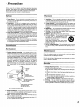
Precautions Before using this umt please read these operating instructions carefully. Take special care to follow the warnings indicated on the unit itself as well as the safety suggeshons listed below. Afterwards keep them handy for future reference. Safety Placement 1. Power Source -- The umt should be connected to power supply only of the type described in the operating instructions or as marked on the unit. 1.
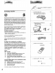
_iiiiiiiiiiiiii_ii_i_ii_iiiiiiL_iii_iiiiii;iiiiii!_!_!;!_!;!i!_!i!i!iiiii_iii_i_i_i_ii_!_iiii_iiiiiiiiiiiiiiiii_iiiii_iii_i_iii_i_ii_i_ii_ Please check and identify the supplied accessories Listening caution [_ AC power supply cord (For USA: SJA172-A or SJAr 72-1) (For Canada: SJA172-A or SJA172) [_ AM loop antenna set (RSA0010) • AM loop antenna ........................ • AM antenna holder ...................... • Screw .................................. 1 pc. 1 pc. 1 pc.
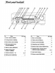
/ No. Name Re?. page No. Name Re?.
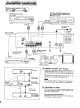
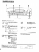
I White Stereo (L)_ connection Red (R) cable (not included) IC_ I Tape deck, second VCR (audio line only) or digital compact cassette deck (DCC) (not included) CD changer (or CD player) (not included) REC (IN) i i I t OUTPUT AC power cord (included) Household AC outlet Only for turntable with ground terminal (AC 120 V/60 Hz) \ Connect this cord after all other cables and cords are connected. REMOTE CONTROL OU] I Antenna terminals i_ A_, I"v At.. OtJlL[] Speaker terminals See page 9.
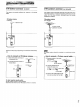
FM indoor This antenna casts. antenna is normally sufficient i.cl. ed) for reception _FM outdoor of FM broad- The outdoor antenna should be used when using the main unit in mountainous areas or in spaces enclosed by reinforced concrete where the FM indoor antenna (included) does not provide satisfactory reception. FM Indoor antenna FM outdoor antenna (included) (not included) /"-_,,-- Adhesive .ot i,,cl.
AM loop This antenna casts. antenna is normally AM J.cl.ded) sufficient for reception of AM broad- outdoor antenna The outdoor antenna should be used when using the main unit in mountainous areas or in spaces enclosed by reinforced concrete where the AM loop antenna (included) does not provide satisfactory reception. AM loop antenna (included) AM outdoor antenna (not included) Vinyl-covered wire (not included) AM ANT AM loop antenna (included) AM AI_ AM LOOPANT AM LOOPANT L. (noti.eJ.
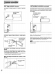
Right speaker Leftspeaker (not included) 1 ,i,Twist 3 2 15 mm (not included) j m! To prevent damage to circuitry, never short-circuit positive (+) and negative (-) speaker wires. • "B" terminals For connection to a second pair of speakers. •Speakerimpedance The impedance ohms.
] 3 2 5 I o '.'': ...... O 0 O- ,,.c_a © __J L__ POWER Before operation, VOLUME TAPE/VCR 21DCC set VOLUME to the "0" position. ..... _WER..... Press PovvER Start the desired source. to Switch on (Refer to the appropriate structions for details.) the power. _ S_AKE_ .... Press A and/or ('_ Bt0 the speaker system(s) to be _J used. _ VOLU'ME ........ Turn voLUME A and B reler to the speaker terminals at the rear of the unit.
SPEAKERS MUTING VOLUME © t I J I tJ ....J i I-1 TM ...... 1-BALANCE BASS Headphones (not included) Plug type: 1/4 inch phone plug stereo type To adjust BASS Q_ the tone quency To mute quality Turn BASS to adjust © the Iow-fro- (3 TREBLE © the sound MUTING Press MUTING. sound. FM TREBLE © level I II I, I MHz MLITING flashing Turn TREBLE to adjust the high.fre. quency sound. Press once again to return to the previous volume level. (The muting indicator will turn off.
Direct access tuning Specify the frequency using the numeric to the desired broadcast station. buttons to directly tune 0 !r-q I ........ 5 i _ .... 66 !,I,;0, 1 I !: C)L_____J' 2 AUTO/MONO FM 3 Press TUNER. TUNER L BANO J Press BAND to select "FM" or "AM". _ T IIII I I._1I._l, I .., III1,11 I I I I ... Illuminates DIRECT TUNING [_ Press DIRECT TUNING. ........................................................................................................................
Sequential If the frequency ching. tuning is not known, use the tuning control for sear- .... 0 5b _B © I -, I_1 .... l_I _ t__.__j' _2 "-t ,., 2 TUNER p, I 'r°'" [ gO % L BAND Press BAN D to select "FM" or "AM", I [ gO FM I II I II iM I_lllllll_ll I I, I I MS, I MHz ! ! Illuminates r / v TUNING ^ n -,, - Press V or A to tune to the desired _-_.,z-- _____ I_ /J oroaacasz, lgO II I _ .
Preset tuning By presetting the desired broadcast stations into the memory channels of this unit, broadcast stations can be selected simply by pressing numeric button(s). (Refer to page 15 for tuning.) -Before Automatic memory presetting J presetting How many broadcast stations can be preset? A total of 30 FM and AM stations can be preset. How is presetting done? The two following methods are available.
Manual memory presetting To listen 660 5 db rlm]W Io- I 24 _ to preset 5 d-o[ -I='1 2 Q- 1 [ ................. Press BAND to select "FM" I__ _JI11213 ";"Tu"E": ............... ........ SpecifY ihe preset channel I\ 9_L__gJusing the numeric button(s). (Example: Channel 12) [] Set to the desirod br0adcast. i _' L_ I i I_'1-1 'L___J " _'Press'TuNERI [ 3 stations _-_--_E_I I 6(3. _1::_::___ i_ ..................... 15 BANV broadcast (Within 2 sec.) =% ............
Tape recording digital compact on the cassette tape deck or deck (DCC) Before recording, prepare the tape deck or DCC for recording (recording level adjustment, etc.). See the tape deck's or DCC's operating instructions for details. VCR. (VCR audio source 1) recording from an Before recording, prepare the VCR (VCR1) for recording ding level adjustment, input selector setting, etc.). See the VCR's operating instructions for details. (recor- TAPENCR 21DCC J I°0 _; (5-o [_[-I_ I _ I-l II O.
,ilililililiiii_ii, i,_i, _iiiiiiiiiiiil Battery installation Insert the batteries Method included with this unit as shown below. for use Use the remote control within 60 degrees and within 7 meters (23 ft.) facing directly toward the receiver's remote control signal receptor. J .................,., [_ T ......'.. Check the (+) 1-) sides. When you need to replace Use two UM-4 "AAA", Use these batteries IEC R03 (1.5 V) or equivalent batteries.
i!_!_!i!i!'!ii!i!iiiiiiiiiiiiiiiiiiiiiiill _!i __iiiiiiiii _iiiiiiiiiiiiiiiiiiiiiiii!ii!ii!!iL_ __i_i iiiiiiiii!!ii!iiiiii!iii !iiii Remote _ This remote control transmitter can be used to operate otl'ier units manufactured by this company in addition to this receiver If a tape deck andlor CD changer (or CD player) has the appropriate remote control terminal, be sure to connect the connection cables for the remote control as shown on page 6.
a CD changer To operate (or CD player) For detailed information concerning CD changer (or CD player) operation, please read the operating instructions for each unit carefully. Sequential play CD © Direct ), -_ Q access play 1 CD _/DECK O Q-l, r POWER TV VCR CD II_ 1 2 3 _/DECK 7 8 9 0 - 7 MUTING 8 9 0 disc. (only for a Technics CD changer) Play will start from the selected track. OQ 3 5 _DCC /R.SKIP IHIz'/F.
For detailed Information concerning tape deck or digital compact cassette deck operation, please read the ol)eretlng Instructions for each unit carefully. o To operate a cassette deck To listen to tapes Only when using a double cassette TAPE f FC_ER W _)/DECK 1/2 deck Select tape deck (DECK 1 or DECK 2) The remote control indicator of the cassette deck is changed TUNER "_ over each time the button is pressed.
For detailed information concemlng The explanations below are examples 6 of these instructions. To watch TV TV or VCR operation, please read the operetlng instructions for each unit carefully. of operation in the case where a TV and VCR have been connected according to the method given on page broadcasts To watch TV broadcasts Facing toward the TV POWER TM F with a VCR tuner Facing toward the receiver Facing toward the VCR POWER MCR Switch ON the Switch ON the power for TV.
Do notattempt to removethe cover(s)or repair the unityourself. Refer servicingto qualified personnelonly. Bm"=! If you operate a TV, VCR or alternative CD changer (or CD player) using this remote control, the unit may fail to operate due to the differing nature of the remote control signal. If the remote control falls It is necessary to reprogram the signal within the remote control by following this simple procedure.
Before requesting service for this unit, check the chart below for a possible cause of the problem you are experiencing. Some simple checks or a minor adjustment on your part may eliminate the problem and restore proper operation.
• AMPLIFIER Rated SECTION minimum • sine wave Frequency Sensitivity RMS power output 40 Hz-20 kHz both channels driven 0.8% total harmonic distortion 100 W per channel (8 Q) 1 kHz continuous power output both channels driven 0.8% total harmonic distortion 103 W per channel(8 Q) Total harmonic distortion rated power at 40 Hz-20 kHz 0.8% (8 _) half power at 1 kHz 0.07% (8 L3) Dynamic headroom (Power amplifier section) 2 dB (8 Q) SMPTE intermodulation distortion 0.