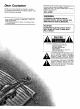
- Technics AV control stereo receiver SA-GX550 SA-GX350 Operating Instructions I he photoglaphs show SA-GX550. Before connecting, operating or adjusting thjs..
Dear Customer The model number and serial number of this product found on either the back or the bottom of the unit. Thank you for purchasing this Technics product. For optimum performance and safety, please read these instructions carefully. Please note them in the space provided them for future reference. MODEL NUMBER ....................................... SERIAL NUMBER ....................................... can be below and retain WARNING: These operating instructions GX550 and SA-GX350.
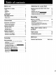
Before use Suggestions Adjusting for safety ........................... Safety ................................................ Installation ............................................ Maintenance .......................................... Service ............................................... Listening caution ...................................... Accessories ........................................ Front panel controls .............................. 4 4 4 4 4 5 5 6 Control section .............
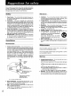
Belore using this unit please read these operating instructions carefully. Take special care to follow the warnings indicated on the unit itself as well as the safety suggestions listed below. Afterwards keep them handy for future reference. Salty Placement 1. Power Source -- The unit should be connected to power supply only of the type described in the operating instructions or as marked on the unit. 1.
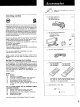
Please check and identify the supplied accessories Listening caution [_] AC power supply cord (For USA: SJA172-1) (For Canada: SJA172) [] AM loop antenna set (SPB1163T) • AM loop antenna ........................ • AM antenna holder ...................... • Screws ................................ @ 1 pc. Selecting fine audio equipment such as the unit you've just purchased is only the start of your musical enjoyment.
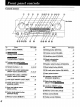
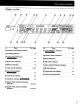
Control section SA-GX550 No. Name Re[. page Power switch (POWER) 14 Tuning control (TUNING) 17 Tuning buttons (TUNING) Tuning mode select button (TUNING MODE) _ 18 17 _) Numeric buttons (1-0) 16,19,20 (_ DOLBY PRO LOGIC SURROUND ONIOFF button (SURROUND) 21,22,23 (_) DOLBY PRO LOGIC 3 STEREO ONIOFF button (3 STEREO) 21,22,23 No.
Display section 7 /" [TAPE MONITOR OVER i-,' NO. / DE It: ,o-:;. Nalne I No. Re?. page 2_ Remote control signal receptor n (_ Name Low impedance Re[. page indicator 14 i,._,_,Xt.
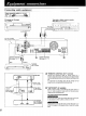
Connecting audio equipment I White tereo (L) connection Red (R) cable (not included) CD changer (or CD player) (not included) Tape deck or digital compact deck (DCC) (not included) [[ oo REC (IN) PLAY (OUT) cassette l] o@@@ oo oO O O_ rn [ZZIIZ c:]z:] i El i OUTPUT L Only for turntable with ground terminal • TAPE/DCC ACOUTLET_ (_) (_ REMOTE CONTROl OUT @@ ® 1 _ Speaker terminals See pages 12- 13.
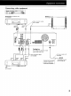
Connecting video Stereo connection Red equipment cable (not included) [ I (R) Second VCR (for playback (not included) Monitor TV only) jr (not included) Video connection cables not included) VIDEO IN AUDIO OUT VIDEO OUT _Q O@ o@ o4,0 @ 13/ VCR2 "--IMONITOR IN IN I OUT ACOUTLETS @ VCR1 IM ! Cooling fan The cooling fan operates at high power output levels only.
FM indoor This antenna casts. is normally sufficient FM ti.cl.aed) antenna for reception of FM broad- outdoor t.ot included) The outdoor antenna should be used when using the main unit in mountainous areas or in spaces enclosed by reinforced concrete where the FM indoor antenna (included) does not provide satisfactory reception.
AM loop This antenna casts. antenna is normally _i.cl.aea) sufficient AM for reception ol AM broad- outdoor antenna _.ot i.ciudea) The outdoor antenna should be used when using the main unit in mountainous areas or in spaces enclosed by reinforced concrete where the AM loop antenna (included) does not provide satisfactory reception.
Placement Connection of speakers of front Right speaker (not included) As well as enjoying normal stereo reproduction with both the left and right front speakers connected, a center speaker and rear speakers can also be connected to the main unit in order to enjoy playback with a feeling of presence using the Dolby Pro-Logic speakers Left speaker (not included) Systems. The illustration below shows where to place the speakers when enjoying sound with Dolby Pro-Logic systems.
Connection of rear Right speaker (not included) speakers Connection Center speaker not included) Left speaker (not included) of center speaker Sound will only come out when the SURROUND mode or 3 STEREO mode of the Dolby Pro-Logic System is on. This unit This unit _cluded) Sound will only come out when the SURROUND mode of the Dolby Pro-Logic System is on. If only one of the rear speakers is connected, no sound will come out. Be sure to connect both speakers.
V 2 3 5 0 POWER Belore operation, set VOLUME to the "0" ............ POWE. .... Press _ _ VOLUME TAPE/DCC position. PO WER tO Switch 0n _' ................ Press to seiect source. VCR 1: To watch video tapes (VCR 1) the power. TAPE/DCC- To listen to tape or digital VCR 2" To watch compact videocassette tapes (VCR (DCC)2) The tape monitor indicator will appear. (See below.) CD: To listen to compact discs TUNER: To listen to radio broadcasts [__ [ cJ J sPEAK_-RS ....
BALANCE OMUTING © _PLAKLHS VOLUME / f O 'L'_.... I :T_u.K 0 I LOUDNESS Headphones (not included) Plug type: 1/4 inch phone plug stereo type To listen while to a desired watching audio video 1. Follow steps 1 -2 source BASS TREBLE F---I © © To emphasize low-frequency sound picture LOUDNESS at the left. Press LOUDNESS. _,-,,,UTO 2. Select the desired _liI MANUAL LOCK SPEEAKIERS video source and audio source in step 3 at the left. f";` ,,,, i'"'_ [ .,'-7!2;'.
Direct access tuning Specify the frequency using the numeric to the desired broadcast station. 0 _R C3 buttons to directly tune m:T_ _s © 6 x 32 14 .................................................. :1 • MANUAL LOCK .......... S_EAKE_ m ,_ L_ Press TUNER 1r......... BAND ............ I Press "AM" BAN D tO select ,_ "FM " ""o'r ......... :.F_:....................... ...... _.::::_ _.::::; I m illu:!nate Press DIRECT ' ..... • DIRECTTUNING L" L...J L...I I.....!. TUNING. s L..
Sequential tuning If the frequency ching. Auto is not known, use the tuning control for sear- Manual tuning This automatically searches for broadcast strong signal reception. TUNING TUNING stations which provide tuning The frequency trol is turned. will change only by the amount that the tuning con- MODE Q ) 6 ) 432 _._ 1 "_' 432 _ Press TUN ER: ................. 1 '_" 'Press TUNERI ................. ..... BAND ...... Press BANDto _ BAND Select "FM' Press or "AM".
Sequential Preset tuning If the frequency ching. is not known, use the tuning buttons for sear- J tuning By presetting the desired broadcast stations into the memory channels of this unit, broadcast stations can be selected simply by pressing numeric button(s). (Refer to page 20 for tuning.) -Before presetting How many broadcast stations can be preset? A total of 30 FM and AM stations can be preset. How is presetting done? The two following methods 3 2 are available.
Automatic J memory presetting Manual f memory presetting J _ [ 2 /_ 1 4 '_' ' Press 52 ]_ TUNERI ................. BAND Press BAND to select "FM" (_ or ................ t_ Pres,,:ru,E,:................. ... B:','ND ....... Press BANDto select ,FM,, or "AM". Press MEMoRYuntlithe I...._.,11 _I_ "_ 1 4 "AM". Settothe you frequencY which want to from start automatic memory presetting. (Refer to page 16.) ,4 _ .... _ I.._.._ ©:!: ...... ] fre. ................
Preset tuning To listen _co...ued_ to preset broadcast stations S D @ oo 2 _ 2 1__ /.__J " _' 1 "Press _ :FUNERI ................. specify the preset channel using the numeric button(s). (Example: Channel 12) [] ,_i2j (Within 2 sec.) MANUAL LOCK ..... SPEAKE"S =,.Au'ro ! /.....i L.. / / i i\.!./ _Oj/ /1\ b AUTO MANUAL LOCK _b_ ....... / ..... i ..,./ ...
By combining front (A or B), center and rear speakers, SURROUND mode which conveys a feeling of presence or 3 STEREO mode which conveys a feeling of orientation can be enjoyed. Setting the center mode For Dolby Pro-Logic systems, center mode setting is necessary to play back bass sounds effectively. Set the center mode in accordance with the size of your center SURROUND speaker.
Adjusting lVlVh the delay time [q imqll ,_,l,_l_ -,v,vnI i'lk1.ll "! :[O]U _I iii]n Adjust so that oriented. the sound trom the Adjusting speaker _ rear speakers is correctly the output level of each In order to reproduce the feeling of movement of the sound and clear orientation of sound, it is important to correctly adjust the output levels of each speaker. Adjust to the correct levels while listening to the test signal• TEST J J _r @ 1 _J to turn on the SURROUND mode. \ L...
Enjoying with SURROUND 3 STEREO { 6")i _Jt._ .... V0LUME ..... TUrn ///'_'_'_ '/ )' VoLuME t0 set or the volume level normally used for enjoying the source. J CENTER LEVEL Press CENTER LEVEL (-) (+) to adjust the output level (+) or REAR LEVEL (-) or balance. L__ I_"lll :l :[Olll or _ I Illil_ Go ,_,_; i_ REARLEVEL I - I + I While standing in the listening area, adjust the output levels of each 1 [_7 : Decrease the output level. speaker until they are all identical.
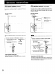
Tape recording on the tape deck or digital compact cassette (DCC) Before recording, prepare the tape deck or DCC for recording (recording level adjustment, etc.). See the tape deck's or DCC's operating instructions for details. TAPEIDCC_ J r_ I ,I _ I _1_ 00, _R _S _AKE_ o o , ; '°'"""°'-'- 0 '_'_--_" ,', I .....I / I_ .... __"' S:/:__h.e audi0/vide0s0urce .......................... Follow tape deck's or DCC's operating instructions. Beginyourrecording: ......................
Recording £rom VCR 2 to VCR 1 Before recording, prepare the VCR (VCR 1)for recording ding level adjustment, etc.). See the VCR's operating instructions for details. from an Before recording, prepare the VCR (VCR1) for recording ding level adjustment, input selector setting, etc.). See the VCR's operating instructions for details. (recor- VCR (VCR 1)recording audio source (recor- _-oq _ _ _--- ............. %. ___ I-I-I=l- ( I ................ _QD_ 1 1 "0 -I-II .-" ...... i i / /_ ...
To record picture from VCR 2 and sound from a different audio source Do not attempt to remove the cover(s) or repair the unit yoursell. Refer servicing to qualified personnel only. Product Before recording, prepare the VCR (VCR 1) for recording (recording level adjustment, input selector setting, etc.). See the VCR's operating instructions for details. J _E5 I I 1 _,' ". 2 Press VCR 2. L_ sPE_.s "0'° _[_ __Seiect ! / !..... // /..... _' th; aud,o be recorded. , ......
Before requesting possible cause of checks or a minor blem and restore service for this unit, check the chart below for a the problem you are experiencing. Some simple adjustment on your part may eliminate the proproper operation.
• AMPLIFIER Rated SECTION minimum • sine wave RMS power output 20 Hz-20 kHz both channels driven 0.05% total harmonic distortion [SA-GX350] 100 W per channel (8 _.) [SA-GX550] 1 10 W per channel (8 _) 1 kHz continuous power output both channels driven 0.05% total harmonic distortion [SA-GX350] 103 W per channel (8 Q) [SA-GX550] 115 W per channel (8 Q) Total harmonic distortion rated power at 20 Hz-20 kHz 0.