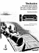
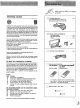
Technics AV control stereo receiver SA-GX770/SA-GX670 SA-GX470/SA-G9057 Operating "_:" p ,. , . ,: °, "; ,,.... ": Before €onnecting, ._ please read'these " " ' "i i"_ ''_'°:' ,', Instructions The photographs o"petaflng instructions ' " "'"'' show SA-GX770 or adjusting this _roduct, completely.
Dear Customer Thank you for purchasing this Technics product. For optimum performance and safety, please read these instructions carefully. These operating instructions are applicable to models SAGX770, SA-GX670, SA-GX470 and SA-G9057. These operating instructions, however, are intended primarily for model SA-GX770. Before use Precautions ........................................ Accessories ........................................ Front panel controls ..............................
Adjusting the sound The model number and serial number of this product can be found on either the back or the bottom of the unit. field Enjoying sound with DOLBY PRO LOGIC ..... 21 SURROUND .......................................... 3 STEREO ............................................ 21 21 Setting the center mode ............................... Adjusting the output level of each speaker ............... 21 22 Adjusting the delay time Ik'lr__-'le#_q,TJ-z,]-,lql Enjoying with SURROUND or 3 STEREO ...
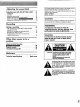
Before using this unit please read these operating instructions carefully. Take special care to follow the warnings indicated on the unit itself as well as the safety suggestions listed below. Afterwards keep them handy for future reference. Placement Power Source -- The unit should be connected to power supply only of the type described in the operating instructions or as marked on the unit. 2.
Please checkandidentify thesupplied accessories Listening caution D @ AC power supply cord ....................... (For USA: SJA172-A or SJA172-1) 1 pc. (For Canada: SJA172-A or SJA172) Selecting fine audio equipment such as the unit you've just purchased is only the start of your musical enjoyment. Now it's time to consider how you can maximize the fun and excitement your equipment offers.
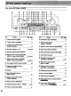
For SA-GX770/SA-GX670 i No. Name Re[. page No. i Name Re[.
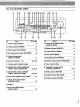
For SA-GX470/SA-G9057 z I m_ I I I i I I , i ÷ I ....I.... Name No. Ref. page (_ Power switch (POWER) 14 (_ Tuning control (TUNING) 18 (_ Band select button (BAND) 16 (_) FM mode select button (FM MODE) 16 (_ Direct tuning button (DIRECT TUNING) Numeric buttons (1-0) 16 16,19,20 DOLBY PRO LOGIC 3 STEREO ONIOFF button (3 STEREO) (_ Test signal ONIOFF button (TEST) Center level adjust button (CENTER LEVEL) Name Ref.
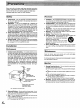
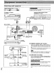
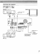
Connecting audio equipment _wli3ni'_ Stereo connection cable (not included) WhiteRe d (L)(R) _) I_._l_l[e:t;,_ iF4 Do not place books etc on top of this unit so that the heat radiationvents remain unblocked i_ CD changer (or CD player) (not included) Tape deck or dlgltal compact deck (DCC) (not included) cassette REC (IN) PLAY (OUT) n i i i OUTPU_L_ '_-( Only for turntable with ground terminal \ I GNDSeeAntenna terminelSpages 10 11 [] "REMOTE Connect CONTROL the connection OUT" termina
Connecting video Stereo connection White Red equipment cable (not included) (L)_ (R) Second VCR (for playback (not included) I I only) Monitor TV (not included) connection cable included) VIDEO IN AUDIO OUT VIDEO OUT I_.
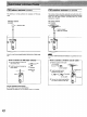
FM indoor This antenna casts. FM Indoor antenna is normally ¢i.cl.ded sufficient for reception FM of FM broad- antenna outdoor antenna .ot i.c .ded The outdoor antenna should be used when using the main unit in mountainous areas or in spaces enclosed by reinforced concrete where the FM indoor antenna (included) does not provide satisfactory reception. FM outdoor antenna (included) (not included) /"" _ Adhesive tape t 75-ohmscoaxial (not included) _.. 75_ I _1_'%)I I..
AM loop antenna This antenna is normally casts. (i.et.d d) AM sufficient for reception of AM broad- outdoor antenna The outdoor antenna should be used when using the main unit in mountainous areas or in spaces enclosed by reinforced concrete where the AM loop antenna (included) does not provide satisfactory reception. AM loop antenna (included) AM outdoor antenna (not included) Vinyl-covered wire (not included) AMANT AM loop antenna , (included) AN AM LOOPANT L.. (.
Placement Connection of speakers of front Aswell as enjoyingnormalstereo reproductionwith boththe left and right front speakersconnected, a center speaker and rear speakerscan alsobe connectedto the main unit inorderto enjoy playbackwith a feeling of presence usingthe Dolby Pro-Logic Systems. The illustration below shows where to place the speakers when enjoying sound with Dolby Pro-Logic systems.
Connection of rear Right speaker not included) speakers Connection Left speaker (not included) of sub woofer The sub woofer is connected when bass sounds are inadequately reproduced because front speakers are too small. When connected, the sub woofer can be placed in any position. This unit has no amplifier section designed especially for the sub woofer, so it is necessary to purchase a sub woofer with a built in amplifier or buy the two separately.
] 3 2 5 VCR 2 INPUT J VOLUMe [] O I i , i, i , i, I ; , i" I o I. ,l l POWER i , i.;,io i.-J:_ o I,-J-I VOLUME TAPEIDCC VCR 2 front input terminals Before operation, set VOLUME to the "0" position. 'tO"seiect 'the des'ired __Press source. _kk_ / _ the speaker system(s) to be used. _" "_ A and B refer to the speaker terminals _.J at the rear of the unit. I.... o_ If you use the VCR connected to the VCR 2 front input terminals, press VCR 2 INPUT to the "FRONT" position.
ll,]_,__'._4h[Olk.'.#,__:(;Jri(i Ile ] i_"l'_'1[el)[_ IF4oI_'_'__._DI;9 TREBLE BASS BALANCE SPEAKERS SPEAKERS VOLUME O O VOLUME J __, - ....:....:......:...._, _.___. TF'_(not=luOeO> -.O,,NG/ u, To listen while o,o;L = to a desired watching audio source __ Headphones | f _(not included) Lll1 -MUTING BALANCE r 1/4 inch phoneplug mlP'"g type: To adjust O I_ stereo type the sound balance BALANCE a video the Select the desired video source source in step 3 on the left.
Direct access tuning Specify the frequency using the numeric buttons to directly tune to the desired broadcast station. I;1,]m_.'%_e):_V/ol/_ f_'_.e'DIol,_ =[,] R,._.,I[etNrB/oIb'IL,_O;(,'Ir4_ J C J i I i'b"[ _ I _,°' I _O-I ,.,,,,r.,, °. ............ __1_-_-'-' ' =" '"; _-"_ - ,,Io. T_IIII-I=,I FM MODE - tTI-I I 3 2 The procedures I_1 ] 4 2 I J ]-- "- FM MODE I 3 14 described below are an example of SA-GX770/SA-GX670. , Pr... I° , _' :/ PAM._,,,_ _(" .,,_. /.-.._ f...
Sequential If the frequency ching. Auto n_,]_-v,.1_:_m_o_'_,_I_:(.Ti[0m tuning is not known, use the tuning control for sear- tuning Manual This automatically searches for broadcast strong signal reception. stations which provide tuning The frequency trol is turned. will change only by the amount that the tuning con- TUNING J J D ,,_o- ,....____... 4 32 1 432 1 pr,. ................. .....B.._" .......P;''" ei._ii_ to,.;ec;,;i=M,, _ ....B,_N;_ ........PF;;,_. Bi,i'ii_io',*i*_t,;i:_i.
Sequential If the frequency ching. tuning Preset is not known, use the tuning buttons for sear- By presetting the desired broadcast stations into the memory channels of this unit, broadcast stations can be selected simply by pressing numeric button(s). (Refer to page 20 for tuning.) -Before J tuning presetting How many broadcast stations can be preset? A total of 30 FM and AM stations can be preset. How Is presetting i=_o-6t--'.i=i T -_ 2 3 done? The two following methods are available.
Automatic memory Manual presetting memory presetting J J i ©o°' 001 .D i I i ........... @ _ _ I T-[i--]'l" I .Q.Q @.©_.@. [_' ................ ................ desire_J ' broad. (Follow steps 1 through 4 on page 16 or 17 or steps 1 through 3 on page 18.) You can also set the stereo mode to the monaural _ position. i ,,_._ i P;..__MeM0"Y m0m'"t,rJ- .....E_.Y P;,5M'eeORYu"t"th'iie' _," i quency begins to change. [,, / ',,,_Y (Automatic start.
Preset tuning To listen _ontl.uem to preset broadcast stations f : I ,i,i ........ =. ';':, :'7'.r'W'_ I-I-I-I N w __,_ Q 0 ©_© / __speclfy the presei channei using the numeric button(s). _,_ (Example: Channel 12) [] (Within 2 sec.) MANUAL LOCK I sPE_
Enjoying sound with DOLBY By combining front (A or B), center and rear speakers, SURROUND mode which conveys a feehng of presence or 3 STEREO mode which ,conveys a feehng of orientation can be enloyed PRO LOGIC Setting the center mode For Dolby Pro-Logic systems, center mode setting is necessary to play back bass sounds effectwely.
Adjusting the output level oF each speaker In order to reproduce the feeling of movement of the sound and clear orientation of sound, it is important to correctly adjust the output levels of each speaker. Adjust to the correct levels while listening to the test signal. , , vo,u_ ..... Turn'V'oLOME ' io "set used the volume level normally '(_ TEST "E _ Ii I _." for enjoying the source. p.,,, CEN+E,LE VELi: iO . ". I - I * I (+) or REARLEVEL (-) or (+) to adjust the output level L_ .
Adjusting the delay Enjoying with SURROUND 3 STEREO time [,..1'z_[_[_i4olb.-]r_,1[e-)[(w4i=,] nuL, _ "it_l_' -va ea=ll-_l.gl:!=[gill _,I hi.] iZL_I Adjust SO that the sound from the rear speakers oriented. or is correctly J u w I ..... I==i I 1 _ IJ I D. _ _ _., _,/ _j __.....i j// _ n .=_ : [_ ,u.._ND ....Pr;;" SbRnOONb or STEREO to turn desired mode. __-" Do_ For SURROUND _- ............ _............ or DELAYTIMEPress DELAY TIME to set to [ .5_5655_ 1 2 su._.o .I...
Tape recording digital compact on the tape deck or cassette deck (DCC) Before recording, prepare the tape deck or DCC for recording (recording level adjustment, etc.). See the tape deck's or DCC's operating instructions for details. VCR (VCR audio source 1) recording £rom an Before recording, prepare the VCR (VCR1) for recording ding level adjustment, input selector setting, etc.). See the VCR's operating instructions for details. (recor- TAPE/DCC r 1 6," °. __'_ I, I _!__ [""1@66 t .....
Recording from VCR 2 to VCR 1 Before recording, prepare the VCR (VCR 1) for recording ding level adjustment, etc.). See the VCR's operating instructions for details. (recor- To record picture from VCR 2 and sound from a different audio source Before recording, prepare the VCR (VCR 1) accordingly (recording level adjustment, input selector setting, etc.). See the VCR's operating instructions for details. There are VCR 2 terminals at both the front and rear of this unit.
If you make a mistake in operation or if sound output stops due to some operation which was performed, the HELP function displays characters which can be useful for indicating the method by which this condition can be remedied. If "ERROR" or scrolling characters (for instance, "TAPE MONITOR ON NOW") appears on the display during operation, carry out the following operation. - HELP --RESET / m ..... D ,,0o. Press -HELP momentarily. The method for remedying this condition will be displayed.
Before requeshng serv}ce for thts umt, check the chart below for a possible cause of the problem you are experiencing. Some simple checks or a minor adjustment on your part may eliminate the problem and restore proper operation.
• AMPLIFIER SECTION Rated minimum sine wave • RMS power output 20 Hz-20 kHz both channels driven 0.05% total harmonic distortion [SA-GX770] 125 W per channel (8 Q) [SA-GX670] 110 W per channel (8 Q) [SA-GX470/SA-G9057] 100 W per channel (8 _) 1 kHz continuous power output both channels driven 0.05% total harmonic distortion [SA-GX770] 130 W per channel (8 Q) [SA-GX670]115 W per channel (8 Q) [SA-GX470/SA-G9057]103 W per channel (8 Q) Total harmonic distortion rated power at 20 Hz-20 kHz 0.