
Operation Manual


---
--
We
want
to
thank
you
for
selecting the
SL
·
1100
DIRECT
DRIVE
PLAYER
SYS
T
EM
.
To receive
optimum
performance
from
the
SL·l100,
we
rec o
mmend
that
you
read these ope
rating
instru
ctio
ns
car
efull
y.
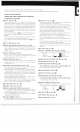
PARTS
IDENTIFICATION
OPERATION
AND
FUNCTION OF CONTROLS
(TURNTABLE
SECTION)
o ROTOR
(S
ee
Fig.1-
f)
)
Thi
s
unit
uses a
direct
drive
motor.
Th
erefo
re, the
rotor,
which
is
the
r
otat
ing
part
of the
motor,
is
connected
directly
to
the
turntable
platter.
The
spindle
o f the
motor
and the s
haft
of the
turntabl
e
platter
are the
same.
For
th
is
reason,
to
maintain
the
high
performance
described in
the
specificat
ions,
it
is
not
desirable
to
appl
y a large am
ount
of ex·
ternal force to the ro
tor
and the spi
ndle
of
the
motor
.
The
rot
or
is,
theref
or
e, clamped securely to
protect
the
deli
ca
te
an
d
important
parts
during
transportation.
Be sure to
remo
ve these
fittings
~
carefully,
and
save
them
fo
r
future
use,
as
w hen,
for
exalnple,
the
player
must
again be
transported
.
(C
autio
n)
The
rotor
of
the
motor
is
constructed
so
th
at
it
cannot
be re
moved
in
ord
er
to
maintain
its
high
perf
or
man
ce
for
a long
time
.
Do
not
attempt
to rem ove the removal
prevention
fitting
@
for
the
rotor
.
6PILOT
LAMP
(Se
e Fig,1- 6 )
€)POWER SWITCH/SPEED SELECTOR (S
ee
Fig,1- €) )
Set the "speed
se
lec
tor"
to
the desired posi ti on
(33
or
45
,
depending
upon
the speed of
th
e
record
to
be
played).
The
pi l
ot
lamp
will
be
light
ed.
The
turntable
platter
will
not
rotat
e unless
you
push the
"STAR
T "
button
.
OSTART
BUTTON
(See
Fig_1-
0)
Push the
"STA
RT
"
button
and the
turnt
able
platter
wi
ll
rotate
..
St
arting
ro tation
power
is
large
with
co
m
plet
e
stability
o f speed
reached
withi
n one-half
ro
t
ation
at 33· 1/3
r.p
.m .
0STOP
BUTTON
(S
ee Fi
g,1
- 0 )
Push the " ST
OP"
butt
on
when
you
want
to s
tOP
the
rotation.
The
turntabl
e
platter
will
continue
to
rot
a
te
f
or
a sho
rt
time
because o f
its large
inertial
for
ce.
0VARIABLE
PITCH
CONTROLS
(
Se
e Fig,1-
0)
Adjus
t
the
"variable
pitch
controls"
if
ne
cessa
ry. These are designed
to
provide
adjustment
of
the
selected speed by ±5%.
Select the speed of the
turntable
platter
by
setting
the
"s
peed s
elector"
to the desired
position.
The
rotating
turntable
p
latter
when
illuminated
by
conven
ti
onal
fluorescent
lamp
or
by
neon
lamp
may
show
move
-
ment
of
the marks
on
the
strobo
disc.
if
so,
adjust
the
"variable
p
itc
h
contrOls"
until
the
strobo
marks
are
statio
nar
y .
A
fter
the
necessary
adjustment
has
been
ma
de, the speed
wi
ll
not
change and re-adjus
tment
wi
ll
not
be ne
cessa
ry .
The
s
trob
o
marks
molded
aro
u
nd
the
turntabl
e
platter
are used
to
check th e correct speed
of
rotation
for
50
H z
(European),
and
60
Hz
(U.S .A .
).
Adjust
it
s
rotation
according
to the s
trobo
label.
OSTROBO
MARKS
(S
ee
Fig.1- 0 )
(l)STROBO
LABEL
(S
ee Fig.1 - (l) )
0SPEED
AD
JUSTMENT SCREWS (S
ee
Fig.1- 0 )
If
.
for
any
reason, the
adjustment
ca
nnot
be successfully
made
,
use
a (- )
tip
scre
wdriver
to
adjust
the
appropriate
speed a
dju
stmen
t screws
(33
or
45
) loca ted beneath the
turntable
platter.
Turn
ing
th
e speed
adjustment
screws
to
the
right
or
left
wi
ll increa
se
or
decr
ease
the speed respective ly.
CDA
C
OUTLET
~(See
Fig.1-
aD
)
Thi
s one is designed w
ith
a view
to
future
us
e,
that
is
for
your
special
co
nv
enience such
as
for
neon lamp or
stylus
illumination
light.
4J)SPECIAL
OIL
(See
Fig.1 -
4J)
)
Th
e bearing
part
s
of
this set are
de
signed
wi
th
an
ultra
·
pre
scise
fin
ish
to
prevent
the
generation
of
"Wow
a
nd
Flutter".
A special
oil
has
been used to
maint
ain the
high
·per
forman
ce
efficiency
of
thi
s set
by
fo
rming
a
unif
orm
film
o f
oil
over
the
parts
. F
or
this
reason,
use
only
the oi l
included
with
this
se
t
for
its
lubri
ca
tion
.
Even
if
there
is
oil
leakage
around
the
oil
hole
or
the
rotor,
ca
used
during
trans
portation
,
it
will
not
effect
the
performance
.
Before
u
se,
apply
about
2
drops
of
oil
into
the
oil
hole.
T o
lubri
ca
te, open the
tip
of
th
e v
essel
with
a needle.
After
lubricating,
cover the
ve
sse
l w
ith
the
cap
to
prevent
the leakage
of
oil.
Never
use
any
other
type
of
oil.
To
lubricate,
remove
the
turntable
platte
r and
apply
about
2
drop
s
of
oil
into
the
oil
hole.
I t
is
sufficient
to
lubricate
the
se
t
once
afte
r
app
r
oxi
mately
2,000
hour
s
of
use.
T
wo
thousand
hours
are
equiva
l
ent
to
5- 1
/2
years,
if
the set is used
one h
our
a
day,
or
to
8
month
s if u
sed
8
hours
a
day.
This
period
is
much
longer than h
as
been necessary
on
previous,
con·
ventional
motors.
Do
nOt
apply
too
much
oil,
nor
more
often
than
necessa ry.
00lL
HOLE
(See
Fig,1- 0 )
ClIOUTPUT
TERMlNALS
(See
Fig.1 -
ClI
. Fig.
3-
ClI
)
Co
nne
ct
the
pickup
co
rds
fr
om
the
a
rm
panel to the
output
termin
al
s.
RED
(R)
IIiII
Channe I
WH
ITE
(L)
o Channel
BLACK
(U
shaped)
-.
H or
I!mDI
(Pickup
Earth)
«II
SCREW
HOLES
(FOR
ARM
PANEL
)(See Fig.1- «II)
epTURNTABLE
MAT
(S
ee
Fig,1-
ep
)
4(jTURNTABLE
PLATTER
(S
ee Fig.1-
4(j
)
Th
e tu
rntable
platter
is a
35
cm
(1
3-25/3
2")
u Itra·large
diameter
2kg
(4.4
Ib)
weight
and
has
inertial
moment
of
32
0kg
·cm
2
(109
.5 Ib-in
2
).
Each
turntable
platter
is
dynamic
a
ll
y balanced.
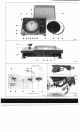
4D
PLA
YER
CABI
NET
(See
Fig.2-
4D
)
4Ji)BOTTOM
COVER
(See
Fig.2-
CE)
)
CP>AUDIO-INSULATED LEGS
(See
Fig.2-
CP>
)
The
a
udio·in
s
ulated
l
egs
are designed
to
el
iminate
vibration
entirely
by
using special
material
s inside
them
.
Adiust
the
he
ight
and level
of
the
player
system
by
turning
the
l
egs.
WOUTPUT
TERMINALS
(Se
e Fig,2- W )
C
onnect
th
e pi
ckup
cords
provided
in
this
set
to
the
p l
ayer
o
utput
terminals
and
co
nnect
the same cha
nne
l
to
the
amplifier.
R (RE
D)
o
Channe
l
L
(WHITE)
E
(U
s
haped)
--
H
..
Chan
nel
or
6m1
IDAC
OUTL
ET @
(See
Fig.2- ID )
~
AC
POWER
CORD
(See
Fig.1-
~
)
~
DUST
COVER
(See
Fig.1-
~
)