MS11-20-1.qxd 20.09.
MS11-20-1.qxd 20.09.00 12:57 Seite 2 Contents 1 2 3 3.1 3.2 3.3 3.4 4 4.1 4.2 5 5.1 5.2 5.3 5.4 5.5 6 7 8 9 F un ct io n . . . . . . . . . . . . . . . . . . . . . . . 2 S a fe ty Ad v ice . . . . . . . . . . . . . . . . . . . 3 I nt r od uc ing t h e co m p on e n t s . . . . . . . . . 3 GigaSwitch 11/20G . . . . . . . . . . . . . . . . . . . . . . . . . . . . . . .3 GigaSwitch 11/20K . . . . . . . . . . . . . . . . . . . . . . . . . . . . . . .3 Intermediate Amplifier 9Z . . . . . . . . . . . . . . . .
MS11-20-1.qxd 20.09.00 12:57 Seite 3 2 Safety Hints For your own protection, you should read the safety hints carefully before installing the GigaSwitch multiswitch. The manufacturer accepts no responsibility for damage caused by non-observance of the safety hints, or by inappropriate handling. > > > The components must be mounted in dry rooms on flat, non-flammable surfaces. Air circulation slots on the components must permit unimpeded circulation.
MS11-20-1.qxd 20.09.00 12:57 Seite 4 3.3 Intermediate Amplifier 9Z (Part No. 000/3231) The intermediate amplifier 9z has been designed to compensate for the damping effect of 25m of multimedia cable, or of 40m of CoaxSat 2150 cable, when used to transmit satellite signals. The amplification of terrestrial signals can be adjusted. 3.4 Distributor 9V This is used to achieve a three-way split of main-line connections, while providing a high degree of insulation.
MS11-20-1.qxd 20.09.00 12:57 Seite 5 DiSEqC control functions can utilise the 22KHz control signal to switch to the Low Band setting of Eutelsat 13°. All other outputs are fixed in terms of their switching position. The setting of this switch is irrelevant for and not applicable to DiSEqCcompatible receivers. 4.2 Setting of terrestrial Inputs Terrestrial signals can be fed into the system in separate bands, or as a broad band signal.
MS11-20-1.qxd 20.09.00 12:57 Seite 6 5.3 LNBs > > > You may choose quattro, dual output or twin LNBs, but not universal twin types. Use only high-quality LNBs from reputable manufacturers, such as TechniSat Part. No. 0000/8880, providing either linear or diagonal frequency compensation. The output level should be >75 dBµV. The LNBs receive their mains power supply via the basic unit GigaSwitch 11/20G. Please note the maximum power supply as per the technical specifications. 5.
MS11-20-1.qxd 20.09.00 12:57 Seite 7 6 Installation Hints > > > > > > > > > > > We recommend a star-form distribution originating in the attic, or near the centre of the house/building. Please ensure that the levels of the various satellite signals fed into the system are approximately equal in strength. The outputs for participants 5…10 and 16…20 supply a higher output level in the satellite band. You should use these outputs to connect participants with longer cable connections.
MS11-20-1.qxd 20.09.
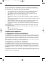
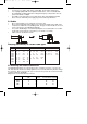
220V AC, max. 40W Max. 20m multimedia cable 9 terminators 75 Ohm F-toF connector 20.09.00 12:57 Max. cable length with 9Z: 35m multimedia cable Max. cable length without 9Z 10m multimedia cable Installation for 80 participants MS11-20-1.
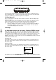
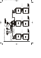
Max. 20m multimedia cable If greater length required, insert Intermediate amplifier 9Z 10m multimedia cable Max. 20m multimedia cable 10m multimedia cable 20.09.00 12:58 10m multimedia cable Adjustable damping unit Part No. 0000/3145 To adjust terrestrial signal level Installation for 120 participtans MS11-20-1.
MS11-20-1.qxd 20.09.00 12:58 Seite 11 8 Troubleshooting guide Problem Possible cause Solution No reception on any polarisation plane > green LED blinking Short circuit in LNB Remove each cable individually, until green LED remains on. Fix short circuit cable section No reception on any polarisation plane > green LED on Antenna adjustment faulty Check signal incoming to LNB. Check that correct LOF setting is set at receiver. Check power supply of LNB at 11/20.
VSWR: on main connections < 2.5, derivatives < 3 from 11/8 G) v. 11/8G: 70mA/13V, 220mA/18V 11/20: 310 x 220 x 50mm 11/20K: 310x305x50mm - >70 dB <4 dB 85 dBµV 90 dBµV 75 dBµV 240 x 85 x 60 mm Ambient temperature: 25...55°C, use inside buildings only, overload protection of inputs and outputs: >/= 5kV 2x300mA and/or 2 x 300 mA from receiver: <50 mA Mains supply 230 V, +/-10%, 50...60 Hz, 25 VA, overload protection and indicator 11.5 V....14 V/ 16 V...