
User's Manual
3-2
Unpack the equipment and check for any damage that may have occurred during transit. Save the
original shipping container for returns due to damage or warranty claims. Check that each item on the packing
slip has been shipped in the container.
3.3 INSTALLATION
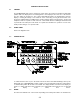
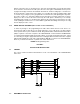
The TDFM-600/6000 Transceiver is designed to be dzus mounted and should be installed in conjunction
with an IN-600 installation kit. See figure 3-1 for an outline drawing of the unit with dimensions to
facilitate the installation.
3.4 INSTALLATION KIT - CONTENTS
The IN-600 installation kit (P/N 01xxxx-1) consists of:
1. One 25 pin Cannon D mating connector (female) complete with crimp pins and hood.
2. 3 BNC connectors.
3.5 ANTENNA INSTALLATION
The type and number of antennas depends on the model of transceiver being installed.
The following is a list of recommended antennas for the various RF modules:
VHF 136 to 176 MHz Comant part # CI-292
UHFLO 403 to 470 MHz Comant part # CI-275
UHFHI450 to 512 MHz Comant part # CI-275
800 806 to 870 MHz Comant part # CI-306
The antenna should be mounted on the bottom of the aircraft whenever possible.
Consult with instructions provided with the antenna. Connect the RF cables to the back
of the transceiver using the BNC connectors provided in the installation kit.