
User's Manual


3-5
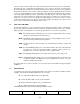
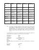
>J1' 25 Pin D Connections - Use FEMALE Connector
25 Panel Backlighting
TABLE 3-1
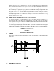
3.7 INSTALLATION - WIRING INSTRUCTIONS
Figure 3-2 shows all required connections and recommended wire sizes for the
TDFM-600/6000 transceiver.
3.8 MAIN GROUND - PINS 1 AND 14
Both pins should be connected to ground. The main ground is internally connected
to the chassis.
3.9 MAIN POWER +28 VDC - PINS 2 AND 15
Both pins should be connected to +28 volts DC +/- 15%.
3.10 MIC 1, 2 AND 3 - PINS 3, 6 AND 9
The microphone input signals shall be connected using shielded wire with the shield
connected to ground (pin 1 or 14). It is recommended for best results to leave the
other end of the shield floating to prevent ground currents.
3.11 AUDIO 1, 2 AND 3 - PINS 4, 7 AND 10
Audio outputs 1, 2 and 3 are 600 ohms impedance. The output power is 500 mW
maximum.
3.12 PTT 1, 2 AND 3 - PINS 5, 8 AND 11
The PTT lines should be floating when in receive and grounded for transmit. The
input has a pull up resistor to 5 volts. Connecting an audio panel which wishes to
see more may result in no receive audio from the audio panel. Connect a 1N4006
diode in series with the cathode towards the audio panel in this case.
3.13 TX DATA AND RX DATA - PINS 12 AND 13
These are an RS-232 serial port for future use. Leave both pins unconnected.
3.14 MEMORY UP AND MEMORY DOWN - PINS 16 AND 17
These pins can be used to scroll up and down through the zone/channel/mode/talk
group selections for the band currently displayed on the screen. The inputs normally
floating are grounded to activate. Two push buttons or a center off, SPDT, spring
loaded toggle switch are typically used on these inputs.