
User's Manual

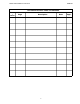

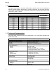
Table Of Contents
- INSTALLATION INSTRUCTIONS
- 1.1 Introduction
- 1.2 Description
- 1.3 Purpose of Equipment
- 1.4 Model Variation
- 1.5 Technical Characteristics
- 1.6 Certification Summary
- SECTION 2
- 2.1 Equipment Packing Log
- 2.2 Transceiver Installation
- 2.3 Installation Kit - Contents
- 2.4 Antenna Installation
- 2.5 Installation - Pin Locations and Connections
- 2.6 Physical Dimensions
- 2.7 Wiring Instructions
- 2.8 Transmitter Side Tone Level Adjustment
- 2.9 Main and Guard Noise Squelch Adjustment
- 2.10 Reference Layouts
- SECTION 3

TDFM-136B Installation Instructions 08RE398
Table of F igu res
Figure 2-1. Transceiver Mounted View of the 15 Pin Connector.................................................2-2
Figure 2-2. Wiring Connections for TDFM-136B Transceiver.......................................................2-3
Figure 2-3. Outline Drawing for TDFM-136B Transceiver............................................................2-4
Figure 2-4. Control points for the TDFM-136B MCU Board..........................................................2-7
Table of Tabl es
Table 1-1. TDFM-136B – Model Variation....................................................................................1-2
Table 1-2. TDFM-136B – General Characteristics.......................................................................1-2
Table 1-3. TDFM-136B – Operational Characteristics.................................................................1-3
Table 1-4. TDFM-136B – Receiver Characteristics – Main and Guard........................................1-3
Table 1-5. TDFM-136B – Transmitter Characteristics..................................................................1-4
Table 1-6. TDFM-136B – Environmental Testing Summary.........................................................1-4
Table 3-1. TDFM-136B - Rear Connector Pin Assignments.........................................................2-2
vii