
User's Manual


3-6
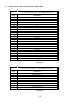
P1 - 15 Pin (high density) D Connections – Use FEMALE
Connector
Pin #
Description
1 4 MHz
2 8 MHz
3 10 MHz
4 20 MHz
5 40 MHz
6 Audio 5
7 No connection
8 No connection
9 No connection
10 Tune Indicator
11 Speaker 5
12 Tune Enable
13 Ground
14 PTT5
15 Mic 5
TABLE 3-3
3.7 INSTALLATION - WIRING INSTRUCTIONS
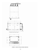
Figure 3-2 shows all required connections and recommended wire sizes for the TDFM-7300 transceiver.
3.8 MAIN GROUND – J1 PINS 1 AND 14
Both pins should be connected to ground. The main ground is internally connected to the chassis.
3.9 MAIN POWER +28 VDC – J1 PINS 2 AND 15
Both pins should be connected to +28 volts DC +/- 15%.
3.10 MIC 1, 2, 3, 4 AND 5 – J1 PINS 3, 6, 9, J2 PIN 6 AND P1 PIN 15
The microphone input signals shall be connected using shielded wire with the shield connected to ground
(pin 1 or 14). It is recommended for best results to leave the other end of the shield floating to prevent
ground currents unless you are connecting to an audio panel with floating hi and lo inputs (like the
Technisonic A710 or A711 series) in which case the shield must be connected to the lo input.
3.11 AUDIO 1, 2, 3, 4, 5 AND COMBINED – J1 PINS 4, 7, 10 J2 PINS 5, 2 AND P1 PIN 6
Audio outputs are 600 ohms impedance against ground. The output power is 600 mW maximum.
Unused outputs do not have to be terminated and should be left unconnected.
3.12 PTT 1, 2, 3, 4, 5 AND COMBINED – J1 PINS 5, 8, 11, J2 PINS 3, 4 AND P1 PIN 14
The PTT lines should be floating when in receive and grounded for transmit. The input has a pull up resistor
to 5 volts. Connecting an audio panel that wishes to see more, may result in no receive audio. Connect a