VHF/AM SINGLE CHANNEL 50 WATT TRANSCEIVER MODEL TSC-4400 P/N 011211-1 Installation and Operating Instructions TiL Document No. 04RE331 Rev. n/c November 2004 Technisonic Industries Limited 240 Traders Blvd., Mississauga, Ontario L4Z 1W7 Tel:(905)890-2113 Fax:(905)890-5338 web site: www.til.
WARNING Do not make physical contact with antenna when transmitter is on. This unit can produce over 50 watts of power when transmitting. CAUTION This unit contains static sensitive devices. Wear a grounded wrist strap and/or conductive gloves when handling printed circuit boards. WARRANTY INFORMATION The rack mounted Single Channel Transceiver, Model TSC-4400 is under warranty for one year from date of purchase.
REVISIONS REV N/C PAGE DESCRIPTION Original Issue DATE 11/04 APPROVED RR HD
TABLE OF CONTENTS Paragraph SECTION 1 1.1 1.2 1.2.1 1.2.2 1.2.3 1.2.4 1.2.5 1.2.6 1.3 1.3.1 1.3.1.1 1.3.2 1.4 SECTION 2 2.1 2.2 2.2.1 2.2.2 2.2.3 2.2.4 2.2.5 2.3 2.3.1 2.3.2 2.3.3 2.3.4 2.4 2.4.1 2.4.2 2.5 2.5.1 2.5.2 2.6 2.7 2.8 Title Page GENERAL DESCRIPTION Introduction . . . . . . . . . . . . . . . . . . . . . . . . . . . . . Description . . . . . . . . . . . . . . . . . . . . . . . . . . . . . Transceiver Module . . . . . . . . . . . . . . . . . . . . . . . . Power Supply Module - P/N 043603-1 . . .
TABLE OF CONTENTS (Continued) Paragraph SECTION 3 3.1 3.2 3.3 3.4 3.4.1 3.4.2 3.4.3 3.4.4 Title Page OPERATING INSTRUCTIONS Introduction . . . . . . . . . . . . . . . . . . . . . . . Installation . . . . . . . . . . . . . . . . . . . . . . . . Operator's Switches, Controls and Indicators Operating Instructions . . . . . . . . . . . . . . . . Transmitter Operation (Local Mode) . . . . . . . Receiver Operation (Local Mode) . . . . . . . . . Switching OFF . . . . . . . . . . . . . . . . . . . . .
SECTION 1 GENERAL DESCRIPTION 1.1 INTRODUCTION This publication provides general information on the VHF/AM Single Channel Transceivers, Model TSC-4400, Part No. 011211-1, manufactured by Technisonic Industries Limited. This document covers the configuration of this equipment that utilizes either of the following remote control cards; p/n’s 923051-1 (standard) or 943180-1 (supplied upon request).
1.2.1 Transceiver Module The Single Channel Transceiver is based on Transceiver Model 90-6R/8.33. The transceiver module is a low power VHF/AM transceiver which can transmit or receive on independent, preprogrammable synthesized frequencies, with 25kHz or 8.33kHz channel spacing in the frequency range 118.000 MHz to 138.000 MHz. The operating frequency can be easily programmed using a PC via the front panel mounted serial DB-9 connector. 1.2.
2. Line Interface Board P/N 943180-1 Provides remote control transceiver operation on 2 wire dedicated 600 ohm lines utilizing the EIA multi-tone keying format found in the Land Mobile Industry. A high level 2175 tone followed by a 1950 Hz guard tone and then a low level 2175 Hz continuous tone is utilized to key the transceiver. The 943180-1 board can also be jumper strapped for standard aeronautical 2175 Hz continuous tone operation. DC (15mA) current loop and ground keying is also supported.
Conference Audio (Optional) 1.3.1.1 NOTE: This feature is only provided upon special order. The component (R7) discussed below is left unpopulated on standard configuration radios. Conference Audio provides the operator with Tx voice on the transceiver speaker when the transmitter is remotely keyed from another location. The audio level of the transmit audio is internally adjustable from 0.0W to 0.5W of audio output.
TABLE 1-2 TSC-4400 LEADING PARTICULARS POWER REQUIREMENTS: AC Input Voltage/Current . . . . DC Input Voltage/Current . . . . ... POWER OUTPUT: Adjustable . . . . . . . . . . . . . . . . . . . Output Impedance . . . . . . . . . . . . . . Microphone Compression Range . . . . . . . . . . Battery Charger Current (48V and 12V, Each) . . . . . . . . . . . . . . 100 to 260 VAC @ 3.5 Amp . . . . . . . . . . . . . . 48 VDC Nominal @ 5.0 Amp . . . . . . . . . . . . . . 12 VDC Nominal @ 5.0 Amp . . . . . . . . .
TABLE 1-2 TSC-4400 LEADING PARTICULARS (Continued) TRANSCEIVER MODULE: Dimensions & Weight: Width . . . . . . . . . . . . . . . . . . . . . . . . . . . . . . . . Height . . . . . . . . . . . . . . . . . . . . . . . . . . . . . . . Depth . . . . . . . . . . . . . . . . . . . . . . . . . . . . . . . Weight . . . . . . . . . . . . . . . . . . . . . . . . . . . . . . . TRANSMITTER: Power Output . . . . . . . . . . . . . . . . . . . . . . . . . . Audio Input . . . . . . . . . . . . . . . . . . . . . . . . . .
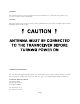
SECTION 2 PREPARATION FOR USE AND STORAGE 2.1 INTRODUCTION This section provides the information required for custom configuration and storage of the Single Channel Transceiver. Custom system configuration includes customizing remote control board functions, and Transmit/Receive frequency selection. CAUTION: Antenna must be connected to transceiver before transmitting or permanent damage to the output stage may occur. 2.2 DISASSEMBLY/ASSEMBLY (Refer to Figure 2-1) 2.2.
Figure 2-1Single Channel Transceiver - Internal View 2-2
(6) Move the transceiver module slightly back from the front panel and disconnect the flat cable connecting the front panel assembly to the transceiver module, audio interface board A3. The connector is located on the A3 board. (7) Lift transceiver module clear of chassis. REPLACEMENT 2.2.3 (1) Position the transceiver module into the chassis.
Figure 2-2 Programming Interface Board with Crystal Filter Option 2-4
REPLACEMENT 2.2.5 (1) Align the two female connectors on the control board with the male connectors on the Mother Board using the four mounting holes and standoffs as a guide. Secure control board to the Mother Board standoffs with four screws and washers. (2) Replace dust cover as described in paragraph 2.2.1. Remove/Replace Crystal Filter Board, p/n 923069 or Jumper Board, p/n 923074 REMOVAL (1) Remove dust cover of unit as described in Paragraph 2.2.1.
A standard 9 pin serial cable must be temporarily connected between the front panel DB-9 connector on the transceiver and the computer serial port. The transceiver is capable of 25 kHz spacing (wide band) and 8.33 kHz spacing (narrow band) channels. The frequency entered will determine whether the channel will be wide or narrow mode, based on the Combined 8.33 kHz/25 kHz ICAO Frequency-Channel Pairing Plan. For example if you program 118.000 into a memory, the transceiver will operate on 118.
2.3.4 Programming a Frequency Having ascertained the desired operating frequency, continue as follows: (1) Run the TDP-90 program on the computer. (2) Click on the Data pull-down list and select the serial port to which the transceiver is connected. (3) Set the program for 1 channel. (4) Turn on power to the transceiver. (5) Click on the Up icon to retrieve the frequencies from the radio. You will see activity in the Terminal window as data is being transferred.
2.4 REMOTE OPERATION SETUP The Procedures listed below enable the user to custom configure the unit for external remote control hardware. Refer to Table 2-3 for connector pin details on Remote Control D Connector located at rear of Single Channel Transceiver. Position Jumpers on Control board as indicated in Table 2-4 or Table 2-5 as required. Refer to Figure 2-3 and Figure 2-4 for board locations. Verify Remote Control operation in accordance with manufacturers instructions.
2.4.1 Two/Four Wire Remote Control Board P/N 923051-1 Provides remote control base station operation on 2 wire or 4 wire, 600 ohm lines. This board can be configured to key the transmitter using a 2175 Hz tone (2380 Hz upon request), plus/minus DC Voltages, ground keying and internal or external current loop keying. Transmit and Receive audio is user selectable for two wires or four wires. Crystals for tone frequencies other than 2175 Hz or 2380 Hz may be obtained by special order.
2.4.2 Two Wire Line Interface Board P/N 943180-1 Provides remote control Base Station operation on 2 wire 600 ohm lines. Two wire Line Interface board with EIA multi-tone, standard 2175Hz continuous tone, DC keying of ground keying over audio lines. The multi-tone keying format consists of a high level 2175 tone followed by a 1950 Hz guard tone and then a low level 2175 Hz continuous tone is utilized to key the transceiver. This board will also support 15mA current loop or ground keying.
Control Configuration for 2/4 Wire (+/-)DC/Ground/Tone/ (Current Loop) Keying Control Board. Assembly #: 923051 R7: R10: R22: R25: R44: SW1: Tx Audio (-25 dBm sensitivity; increases clockwise). 2 Wire Rx Balance @ 600O (1mV RF @ 1KHz, 30% Mod.) R10 adjusted for minimum amplitude at C6/R4 junction. Keying Tone (-30 dBm sensitivity; decreases clockwise). Rx Audio (-10 dBm output level; increases clockwise). Time Out Timer (15 to 300 sec.; 90 sec. Nominal; increases clockwise).
Control Configuration for Multi-Tone Control Board. Assembly #: 943180 R6: R24: R26: R41: R59: R64: Tx audio level adjustment (-25 dBm). Keying Tone Attenuator. 1950 Hz tone level adjustment 2175 Hz tone level adjustment Rx Audio level adjustment. (-10 dBm) Time out timer (90 sec. default) J1: J2: J3: J4: Standard or EIA Keying tone protocol.
2.5 OPTIONAL LOUDSPEAKER, HEADPHONE INSTALLATION Provision is made for connection of an external loudspeaker or headphone to the SPEAKER/PHONE jack of the transceiver, as shown in Figure 3-1. 2.5.1 External Loudspeaker When an external loudspeaker is to be installed, an 8-ohm nominal impedance loudspeaker should be used. The loudspeaker cable should be terminated by a 1/4 in., 3-pole telephone plug (male), with the loudspeaker connected between tip and sleeve (ground).
Figure 2-5Transceiver Adjustments and Settings 2-14
SECTION 3 OPERATING INSTRUCTIONS 3.1 INTRODUCTION This section includes a functional description of each switch, control, indicator and connector located on the front and rear panels of the portable transceiver, including the PRESS-TO-TALK switch located on the microphone. Operating instructions for transmit/receive and the special functions are also included. 3.2 INSTALLATION The TSC-4400 Transceiver is designed to be mounted in a 19 inch rack.
Figure 3-1 Single Channel Transceiver Controls and Indicators 3-2
TABLE 3-1 OPERATOR'S SWITCHES, CONTROLS AND INDICATORS Item No. SWITCHES CONTROLS & INDICATORS FUNCTIONAL DESCRIPTION 1 POWER ON/OFF SWITCH A toggle switch applies the AC power to the power supply and the DC voltage to the transceiver. The transceiver is switched to ON in the toggle UP position the transceiver is switched OFF in the toggle DOWN position. 2 POWER ON LED INDICATOR A GREEN LED Indicates when the POWER ON/OFF switch is set to ON and voltage is applied to the transceiver.
TABLE 3-1 OPERATOR'S SWITCHES, CONTROLS AND INDICATORS (Continued) Item No. 9 SWITCHES CONTROLS & INDICATORS FUNCTIONAL DESCRIPTION RX LABEL Indicates the frequency programmed for receive. 10 LOUDSPEAKER An 8-ohm internal speaker reproduces the receiver audio output. The audio line is disconnected from the internal loudspeaker when the transceiver is operated in Tx mode or when the SPEAKER/PHONE connector is in use.
3.4 OPERATING INSTRUCTIONS NOTE Refer to appropriate Operating Instructions for use with Remote Control Unit. NOTE The following operating procedures are intended specifically for Local Operation. 3.4.1 (1) Ensure that the microphone connector is connected to the MIC/PTT connector of the transceiver. (2) Set the SQUELCH control in the fully counter-clockwise (CCW) position. (3) Set the VOLUME control in the 12 o'clock centre position. (4) Set the POWER ON/OFF switch to "ON".
3.4.2 Receiver Operation (Local Mode) To operate the transceiver in the receive mode, proceed as follows: (1) Ensure that the PRESS-TO-TALK switch on the microphone is NOT depressed, and verify that the Tx ON amber LED is OFF. (2) Verify that the correct operating frequency is indicated on the front panel. (3) Adjust the SQUELCH control to suit local reception conditions.
3.4.3 Switching OFF To switch off the transceiver: (1) Set the POWER ON/OFF on transceiver to switch to OFF. (2) Verify that all indicator LED's on the front panel are OFF. NOTE When the transceiver is switched OFF there is no current drain from external DC. 3.4.4 EXTERNAL DC OPERATION (1) Set AC ON/OFF switch to OFF. (2) Refer to Figure 3-1 for pin locations to hook up external DC Power.
Section 3 Addendum A Til Document No.
This document contains designs and other information which are the property of Technisonic Industries Ltd. Except for rights expressly granted by contract to the Canadian Government, or to the United States Government, this document may not in whole or in part, be duplicated or disclosed or used for manufacture of the part disclosed herein, without the prior permission of Technisonic Industries Ltd.
TABLE OF CONTENTS Paragraph SECTION 1 1.1 1.2 1.3 SECTION 2 2.1 2.2 SECTION 3 3.1 3.2 3.3 3.4 3.5 Title Page GENERAL DESCRIPTION Introduction . . . . . . . . . . . . . . . . . . . . . . . . . . . . . . . . . . . . . . . . . . . . . . . 1-1 Description . . . . . . . . . . . . . . . . . . . . . . . . . . . . . . . . . . . . . . . . . . . . . . . 1-1 Minimum System Requirements . . . . . . . . . . . . . . . . . . . . . . . . . . . . . . . . . 1-1 INSTALLATION INSTRUCTIONS Software Installation . . . . . .
LIST OF ILLUSTRATIONS Figure No. Title 2.1.1 2.1.2 2.1.3 2.1.4 Setup Extraction Dialog . . Welcome Dialog . . . . . . . License Agreement . . . . . Program Installation Dialog 2.2.1 2.2.2 2.2.3 Programming Connections for Mobile transceivers . . . . . . . . . . . . . . . . . . . . . 2-6 Programming Connections for Base Station transceivers . . . . . . . . . . . . . . . . 2-7 Programming Connections for Rack Mount transceivers . . . . . . . . . . . . . . . . . 2-7 3.3.1 3.3.2 3.3.3 3.3.4.1 3.3.4.
Copyright and Trademark acknowledgement - Microsoft, Windows 95, Windows 98, Windows NT, Windows 2000, DCOM, and Internet Explorer are registered trademarks of Microsoft Corporation. - DPL is a registered trademark of Motorola Inc. S Adobe, Adobe Acrobat, and Adobe Acrobat Reader are registered trademark of Adobe Systems Inc.
SECTION 1 GENERAL DESCRIPTION 1.1 INTRODUCTION This publication provides operating and installation information on the TiL TDP-90 Programming Software for 8.33 kHz AM series transceivers. The TDP software allows a standard PC to retrieve data from a connected 8.33kHz AM series transceiver, for editing, storing, and sharing with other 8.33 kHz AM series transceivers. With the TDP software, you can create, save and print archives of your 8.33 kHz AM series transceiver channel settings. 1.
SECTION 2 INSTALLATION INSTRUCTIONS 2.1 SOFTWARE INSTALLATION Before the TDP software can be installed, all of the minimum computer system requirements outlined in the previous section must be met, otherwise difficulty may be encountered during installation or operation the software. The installation procedures outlined in this document assume some basic working knowledge of at least one of Microsoft's Windows 95/98/NT/2000 operating systems.
Figure 2.1.3 - License Agreement In order to Install the TDP-90 Software onto your computer, you must agree to the terms of the license agreement, and confirm so by clicking on OK in the License dialog box. Figure 2.1.
2.1.1 Windows 95 If your computer does not have Microsoft Internet Explorer 5.0 or any other Microsoft application, no later than mid 1998 installed, then it is possible that certain essential system files are outdated. If these system files are outdated your system will not meet the minimum requirements for installing and operating a large variety of new software including the TDP software. If your computer DOES meet the minimum requirements, you may proceed to step 3. 1.
2.1.2 Windows 98 / Windows 2000 Windows 98 comes pre installed with Internet Explorer 5.0 embedded into the operating system. As a result, the operating system as a whole meets the requirements for the installation and operation of the TDP software. 1. To install the TDP software, locate the TDP90_Install.exe file on the CD-ROM using Windows Explorer. When you have located it, double-click it to start the setup process. You will see the first Setup dialog (Figure 2.1.1).
2. After setup finishes unpacking the software, a dialog box will pop up with the option to continue (by clicking on the Next> button see Figure 2.1.4), exit the setup, or at this time you may choose an alternate location for the installation. If you have no objections to the default location just click on the Next> button to continue the installation. 3. The TDP installation will ask what START menu Program Group you want the TDP software shortcut installed.
2.2 HARDWARE INSTALLATION Rack Mount Transceiver: Plug the female end of a 9 pin serial cable into the 9 pin D connector on the front panel of the unit. Connect the other end of the serial cable to an available Serial (COM) Port on your PC. Plug the transceiver into 120VAC and turn the unit on. FIGURE 2.2.
SECTION 3 OPERATING INSTRUCTIONS 3.1 GENERAL This section contains instructions for proper operation of the TDP-90 software and explains the various elements of the Graphical User Interface (GUI). NOTE: The following images are examples only, and may not reflect your particular data settings, or current TDP software version. 3.2 GETTING STARTED To start the TDP-90 in Windows, simply click the Start menu > Programs > TiL Transceiver Data Programmer >TDP-90.
3.3 PULL DOWN MENUS The TDP-90 program has several functions available through the use of pull-down menus. Through these menus, you can invoke file functions, print the channel list, initiate communications with a connected TFM-90 and quit the TDP software. 3.3.1 File Menu Figure 3.3.1 - File Menu Open will allow you to select and load and existing file that was previously saved on disk. The yellow folder icon provides the same function in a single mouse click.
3.3.2 Data Transfer Menu Figure 3.3.2 - Data Menu Download (to Radio) instructs the TDP-90 software to transfer the frequency data in the list to the memory channels in the connected 8.33 kHz AM transceiver. The Dn icon provides the same function in a single mouse click. Upload (from Radio) instructs the TDP-90 program to wait for and read the channel data from the memory channels in the connected 8.33 kHz AM transceiver. The Up icon provides the same function in a single mouse click.
3.3.3 Help Menu Figure 3.3.3 - Help Menu TDP-90-6R Help Contents will start the Windows Help dialog for the TDP-90 software. Here, you will find hardware connection and operating information as well as troubleshooting tips and answers to some Frequently Asked Questions. About displays Technisonic company and contact information as well as the revision number of the TDP software in the “Terminal window” screen.
3.3.4 Channel Selection Figure 3.3.4.1 - Single channel Figure 3.3.4.2 - Six channels The x Channel(s) pull-down tab allows you to select for single or six channel 8.33 kHz AM transceiver use. The frequency editing window changes accordingly. Select “1 Channel TX/RX” for the TSC-4400.
3.4 SAMPLE UPLOAD AND DOWNLOAD 1. Connect the computer to the transceiver and apply power as described in section 2.2. 2. Run the TDP-90 program on the computer. 3. Click on the Data pull-down list and select the serial port to which the transceiver is connected. 4. Set the program for “1 channel TX/RX”. 5. Turn on power to the transceiver. 6. Click on the Up icon to retrieve the currently loaded frequency from the radio. You will see activity in the Terminal window as data is being transferred. 7.