117 HF Reader User Guide Technology Solutions UK Ltd Suite C, Loughborough Technology Centre, Epinal Way, Loughborough, Leicestershire, LE11 3GE, United Kingdom. Tel: +44 (0) 1509 238248 Fax: +44 (0) 1509 220020 Email: enquiries@tsl.uk.
1117 © 2011 TSL. All rights reserved. No part of this publication may be reproduced or used in any form, or by any electrical or mechanical means, without permission in writing from Technology Solutions (UK) Ltd. This includes electronic or mechanical means, such as photocopying, recording, or information storage and retrieval systems. The material in this manual is subject to change without notice.
1117 Contents 1 2 3 4 5 6 7 8 9 Introduction ......................................................................................................................... 4 Parts of the 1117 HF Reader ............................................................................................. 4 Attaching to an MC55/65 .................................................................................................... 5 Detaching from an MC55/65 ................................................................
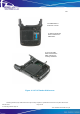
1117 1 Introduction Technology Solutions’ 1117 HF Reader provides the Motorola MC55/65 with HF Radio Frequency Identification (RFID) functionality. The unit attaches as a snap on to the MC55/65. The mechanical design of the unit allows it to be quickly and easily removed. The 1117 HF Reader is powered from the host terminal. 2 Parts of the 1117 HF Reader MC55/65 mating connector Status LED Fixing clip latch SAM slot cover Antenna located on back of unit. SAM slot cover release.
1117 3 Attaching to an MC55/65 1. Align the slots on the side of the terminal with the guides on the fixing clips of the 1117 HF Reader. Fixing Clip Alignment pillar 2. Slide the 1117 HF Reader on to the terminal ensuring the alignment pillar aligns with the holes in the bottom of the terminal. The 1117 will click as it attaches. 3. Slide the fixing clip latch up to lock the 1117 HF Reader on to the terminal.
1117 4 Detaching from an MC55/65 1. 2. Make sure the fixing clip latches have been moved down. Pull the 1117 HF Reader off the terminal. Figure 3: Detaching from an MC55/65 Technology Solutions (UK) Limited reserves the right to change its products, specifications and services at any time without notice. www.tsl.uk.com © Technology Solutions (UK) Ltd Page 6 of 25 1117 HF Reader User Guide V1.2 .
1117 5 SAM Installation or Removal 1. Slide the SAM cover locking clips towards each other 2. Lift the SAM cover away from the reader along the edge by the ActiveSync/Charge connector. 3. Pull the SAM cover away from the reader. Technology Solutions (UK) Limited reserves the right to change its products, specifications and services at any time without notice. www.tsl.uk.com © Technology Solutions (UK) Ltd Page 7 of 25 1117 HF Reader User Guide V1.2 .
1117 The SAM holder is located in a recess 4. Slide the metal clip down to release the SAM holder. 5. Lift up the SAM holder and insert the SAM, ensuring it is correctly orientated. Figure 4: 1117 HF Reader SAM access Technology Solutions (UK) Limited reserves the right to change its products, specifications and services at any time without notice. www.tsl.uk.com © Technology Solutions (UK) Ltd Page 8 of 25 1117 HF Reader User Guide V1.2 .
1117 Refit the cover by reversing the removal procedure: 1. Fold the SAM holder down. Slide the metal clip up to lock the SAM holder. 2. Push the SAM cover in to the reader at a slight angle. There are some small tabs on the cover which align with the slots in the reader. 3. Push the SAM cover flat down on to the reader. 4. Move the SAM cover locking clips apart. 5. Refit the SAM cover locking plate if required.
1117 As an option a locking plate may be fitted to the SAM cover. This is designed to prevent the two cover locking clips from being moved. The cover locking plate is fixed in place with a single screw and should be removed to allow the cover locking clips to be moved and the cover removed. Standard plate Cover locking plate can be fitted instead.
17 6 Charge and ActiveSync Connection The 1117 HF Reader is designed to fit into a standard MC55/65 desktop charge cradle or cradle cup. When docked into a cradle power is passed through the 1117 so that the host terminal can charge. When docked and an external USB host is connected, the USB connection from the host terminal is disconnected from the RFID reader and passed straight through to the connector on the bottom of the 1117.
1117 7 Reading Transponders RFID transponders can be read when they are in range of the antenna. The antenna is located on the back of the 1117 HF Reader. Transponders are read best if they are aligned parallel to the back of the 1117 as shown in Figure 6. Antenna located behind this cover. Figure 6: Antenna location and read direction Technology Solutions (UK) Limited reserves the right to change its products, specifications and services at any time without notice. www.tsl.uk.
1117 8 Status LED The status LED on the front of the 1117 HF Reader provides an indication of the operating status of the 1117 HF Reader. LED colour Status Green flash The previous command was successfully received and processed by the reader. OR. A transponder was read. Red flash The previous command was not successfully processed by the reader. Note that custom configuration of the 1117 HF RFID reader may prevent it from operating as described above.
1117 9 Software 9.1 Driver installation The drivers required for the 1117 HF Reader may be deployed as part of the installation of a custom application. Otherwise they can be deployed by copying ‘RFID Reader Driver.CAB’ to the host terminal and running it. When prompted, choose ‘Device’ as the destination to install the drivers to. RFID Reader Driver.CAB is included on the Explorer Kit and Software Development Kit CDs and can also be downloaded from http://www.tsl.uk.com/downloads.htm. 9.
1117 9.3 SmartWedge RFID application A Wedge application has been developed for use with the 1117 and other Technology Solutions RFID readers. This activates the RFID reader whilst any of the yellow scan buttons are held down. Any transponder serial numbers that are read are sent out as though they had been typed on the keypad to whichever application has focus. Instructions for installing and using the Wedge application are provided separately from the Technology Solutions website at http://www.tsl.uk.
1117 is to be performed. This is the approach taken with the Demonstration application and with SmartWedge RFID. Technology Solutions (UK) Limited reserves the right to change its products, specifications and services at any time without notice. www.tsl.uk.com © Technology Solutions (UK) Ltd Page 16 of 25 1117 HF Reader User Guide V1.2 .
1117 10 Troubleshooting and Maintenance 10.1 Maintenance For trouble-free service treat the 1117 HF Reader in the same way as you would the MC55/65 and observe the following tips when using the 1117 HF Reader: + Do not store or use the 1117 HF Reader in any location that is dusty, damp, or wet. + Protect the 1117 HF Reader from temperature extremes. Do not leave it on the dashboard of a car on a hot day, and keep it away from heat sources. 10.
1117 Symptoms ActiveSync cannot connect to the MC55/65 Possible Cause Action The 1117 HF Reader is not firmly seated into the cradle. Remove and re-insert the 1117 HF Reader from the cradle, ensuring it is firmly seated. ActiveSync is not correctly configured on the PC or the MC55/65. Detach the 1117 HF Reader from the MC55/65 and try to ActiveSync directly to the MC55/65. If this does not work then consult the MC55/65 User Guide.
1117 12 Regulatory information 12.1 Information to the user - FCC This device complies with Part 15 of the FCC Rules. Operation is subject to the following two conditions: (1) This device may not cause harmful interference, and (2) This device must accept any interference received, including interference that may cause undesired operation. This equipment complies with FCC radiation exposure limits set forth for an uncontrolled environment.
1117 (2) l'utilisateur de l'appareil doit accepter tout brouillage radioélectrique subi, même si le brouillage est susceptible d'en compromettre le fonctionnement. Technology Solutions (UK) Limited reserves the right to change its products, specifications and services at any time without notice. www.tsl.uk.com © Technology Solutions (UK) Ltd Page 20 of 25 1117 HF Reader User Guide V1.2 .
1117 13 Technical specifications 13.1 Summary of specifications The following table summarises the 1117 HF Reader’s intended operating environment and technical hardware specifications: Performance Characteristics RF Transmit Frequency 13.
1117 Red, Green LEDs Flash indicating activity (function may also be customised). Connection Interfaces Physical interface USB and power in to charge MC55/65 Reader power supply Powered from host terminal ActiveSync via USB Physical Characteristics Dimensions 85×100×30mm (3.35"x3.93"x1.18") Weight 100g (3.
1117 14 Health and Safety Recommendations Ergonomic Recommendations Caution: In order to avoid or minimize the potential risk of ergonomic injury, follow the recommendations below. Consult with your local Health & Safety Manager to ensure that you are adhering to your company's safety programs to prevent employee injury.
1117 15 Waste Electrical and Electronic Equipment (WEEE) For EU Customers: All products at the end of their life must be returned to TSL for recycling. For information on how to return product please contact TSL.
1117 (iii) which has been subjected to unusual physical or electrical stress, abuse, or accident, or forces or exposure beyond normal use within the specified operational and environmental parameters set forth in the applicable Product specification; nor shall the above warranty provisions apply to any expendable or consumable items, such as batteries, supplied with the Product.