REPORT NO : HCT-F03-1203 FCC ID : RJ5PT4200U DATE :DECEMBER 22,2003 ATTACHMENT D. - USER’S GUIDE HYUNDAI CALIBRATION & CERTIFICATION TECHNOLOGIES CO., LTD. SAN 136-1, AMI-RI , BUBAL-EUP, ICHEON-SI,KYOUNKI-DO, 467-701,KOREA TEL : +82 31 639 8518 FAX : +82 31 639 8525 www.hctec.co.
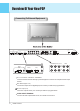
Table of Contents Important Safety Information .......................................................................................................................... 2 Overview Of Your New PDP ............................................................................................................................ 7 Control Button ..............................................................................................................................................
Important Safety Information WA R NING WA R NING : To reduc e the ris k of elec tric s hoc k do not remove c over or bac k. No us er-s ervic eable parts ins ide. R efer s ervic ing to qualified s ervic e pers onnel. T he lightning fla s h with arrow-head within a triangle is intended to tell the us er that parts ins ide the product are a risk of electric shock to pers ons .
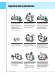
Important Safety Information 1. R ead these ins truc tions All the safety and operating instructions shall be read before the appliance is operated. 2. Retain instructions The safety and operating instructions shall be retained for future reference. 3. Heed all warnings All warnings on the appliance and in the operating instructions shall be adhered to. 4. Keep these ins truc tions All operating and use instructions shall be followed. 5. Follow all ins truc tions 6.
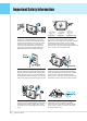
Important Safety Information 4 Provide ventilation for the Monitor. The unit is designed with slots in the cabinet for ventilation to protect it from overheating. Do not block these openings with any object, and do not place the Monitor on a bed, sofa, rug, or other similar surface. Do not place it near a radiator or heat register. If you place the Monitor on a rack or bookcase, ensure that there is adequate ventilation and that you've followed the manufacturer's instructions for mounting.
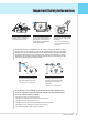
Important Safety Information Do not overload the wall outlet or extension cords. Overloading can result in fire or electric shock. Do not insert anything through the openings in the unit, where they can touch dangerous voltage points or damage parts. Never spill liquid of any kind on the Monitor. Bend antenna cable between inside and outside building to prevent rain from flowing in. - This may cause water damaged inside the Monitor and could give an electric shock. Ground outdoor antennas.
Important Safety Information When replacement parts are required, be sure the service technician use replacement parts specified by the manufacturer or those that have the same characteristics as the original part. Unauthorized substitutions may result in additional damage to the unit. Upon completion of any service or repairs to this Monitor, ask the service technician to perform safety checks to determine that the Monitor is in a safe operating condition.
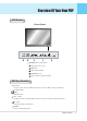
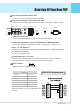
Overview Of Your New PDP OSD Button MENU VOL CH OS D B utton & F unc tion 1 Input S ignal S ource S elect 2 MENU Select 3 Audio Volume Down/Up 4 CHANNEL Down/Up 5 Remoncon Sensor or Power (S tand By) OSD Key Function SELECT S elect the signal source from multiple input source such as TV, VIDEO , S -Video, DTV, DVD , DVI PC and DTV YPbPr. MENU OSD Menu Control. V OL - / V OL + C hange the audio level in normal display mode and move the scroll bar in Volume control menu.
Overview Of Your New PDP Connecting To External Equipment AUDIO COMPONENT(480i/480p/720p/1080i) AUDIO COMPOSITE AUDIO AUDIO OUT OUT SERVICE RS-232C DTV JACK DVI-D(Option) RGB(PC) CVBS AUDIO ANT VHF / UHF + PIP EAR P. IN DVD EXT. SPEAKER + CVBS S-VIDEO SPEAKER SWITCH - - EXT COMPONENT(480i/480p/720p/1080i) AUDIO DTV SERVICE RS-232C INT JACK DVI-D(Option) RGB(PC) DVD R S -232C INP UT C ONT R OL T E R MINA L Control the monitor's functions externally by external equipment.
Overview Of Your New PDP Component Input(DVD Y,Pb,Pr) 480i Connects to a component output terminal of a DVD player. Component Input(DTV Y, Pb, Pr) 480p, 720p, 1080i Connects to a component out put terminal of a Progressive DVD player or HD Set-Top Box. COMPOSITE AUDIO AUDIO OUT EXT. SPEAKER OUT + CVBS ANT VHF / UHF + PIP EAR P. S-VIDEO IN POWER SPEAKER SWITCH CVBS - - EXT INT S-Video Input Terminal Connects to a S-Video output terminal of a S-VHS VCRs or DVD players.
10 OWNER'S MANUAL RS-232C SERVICE JACK DVI-D(Option) RGB(PC) AUDIO DVD DTV COMPONENT(480i/480p/720p/1080i) AUDIO S-VIDEO IN OUT CVBS CVBS COMPOSITE AUDIO PIP EAR P. AUDIO OUT - + - + EXT.
Accessories Table Stand (Separated Type) Remote Control Handset Shielded Alkaline Batteries (AAA) 4*30 : 2EA Screw Power C ord Owner's Manual 4*16 : 2EA F Type Connector OWNER'S MANUAL 11
Features Of The Remote Control When us ing the remote control, always point it directly at the IR s ens or of Plas ma monitor. P R E CH Jump back to previous TV channel ME NU / S E T Activate the OSD window, enter the sub-menu STILL Activate the temporary image freeze feature C H+ / C HChange channel on TV mode, up or down V OL + / V OL Change the audio level, increase or decrease MT S Multi Channel Television Stereo.
Features Of The Remote Control Loading The Batteries 1 Press on the cover and slide in the direction of the arrow. 2 Load two AAA batteries, taking care that the + and - ends face to the correct direction. 3 Close the cover until it clicks.
Monitor Installation The Monitor can be installed in Wall Mount, Table Stand and Ceiling Mount Wall Mount (optional) Installation • Install the monitor only in a location where adequate ventilation is available.
Monitor Installation Table Stand (optional) Installatidfdfdfon United type Table Stand (optional) • Table Stand requires minimum allowable clearances for adequate ventilation.
Monitor Installation Ins tallation 16 OWNER'S MANUAL
Monitor Installation Speaker Installation 42" External S peaker (Optional) Ins tallation + + - - • Match the color of each connection on the speaker and monitor • Turn off monitor power before making any connections . Place the speakers in the position you want. Install the speaker wires on the monitor and speaker. Be sure to connect the positive Ò+Ówire to the Ò+Óinput and the negative Ò-Ówire to the ÒÐÓinput. C onnect left monitor input to left speaker and right monitor input to right speaker.
Monitor Installation External Speaker Accessories 4-Metal Plates (Mount speakers to monitor) 8-4 x 8 Short Screws (Attach metal plates to monitor) 18 OWNER'S MANUAL 8-4 x 16 Long Screws (Attach metal plates to speakers) 2-Speaker Wires
Monitor Installation 50" Speaker (Optional) Installation • Match the color of each connection on the speaker and monitor. • Always lift the monitor itself (not the speakers) when handling or moving the monitor after speakers have been installed. Assemble the monitor to speaker using the supporter hanger and bolt. As shown above A, assemble the a and b of supporter hanger to the monitor using the bolt(M4x8). Assemble the c, d and e to the speaker using the bolt(4x16).