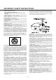
DDR 94 AV Digital Surround Receiver OWNER’S MANUAL CAUTION RISK OF ELECTRIC SHOCK DO NOT OPEN CAUTION: TO REDUCE THE RISK OF ELECTRIC SHOCK, DO NOT REMOVE COVER (OR BACK). NO USER-SERVICEABLE PARTS INSIDE. REFER SERVICING TO QUALIFIED SERVICE PERSONNEL.
IMPORTANT SAFETY INSTRUCTIONS "Note to CATV system installer: This reminder is provided to call the CATV system installer’s attention to Section 820-40 of the NEC which provides guidelines for proper grounding and, in particular, specifies that the cable ground shall be connected to the grounding system of the building, as close to the point of cable entry as practical." CAUTION: < Read all of these Instructions. < Save these Instructions for later use.
Contents TO THE USER This equipment has been tested and found to comply with the limits for a Class B digital device, pursuant to Part 15 of the FCC Rules. These limits are designed to provide reasonable protection against interference in a residential area. This device generates and uses radio frequency energy and if not installed and used in accordance with the instructions, it may cause interference to radio or TV reception.
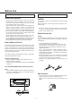
Before Use Read this before operation Before Connection Read this before operation CAUTION < Choose the installation location of your unit carefully. Avoid placing it in direct sunlight or close to a source of heat. Also avoid locations subject to vibrations and excessive dust, heat, cold or moisture. < The ventilation holes should not be covered. Make sure there is enough space above and beside the amplifier/receiver (about 4 inches).
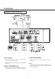
Connection SPEAKERS, PRE OUT, AC OUTLETS Power cord (AC) AC OUTLETS (SWITCHED) Be sure to connect the power cord to an AC outlet which supplies the correct voltage. These outlets are only active when the receiver is turned on. Hold the power plug when plugging or unplugging the power cord. Caution: Make sure that the total power consumption of all equipment connected to the outlets on the receiver does not exceed 100 watts.
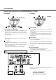
Connection Speaker layout example when using SURROUND MODE or 3 STEREO SURROUND 3 STEREO B A B A C A D (OPTIONAL) C A D (OPTIONAL) B Center speaker Positioning of the Speakers Use magnetic shielded speaker, if you are using it near your TV. Place a center speaker between the front speakers, on or below the TV. This speaker improves sonic imaging and depth of field. Be sure to connect a center speaker when using the 3 STEREO mode.
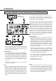
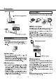
Connection DVD PLAYER, CABLE BOX, SATELLITE RECEIVER (DSS), TELEVISION (MONITOR) If you use both S-Video and RCA composite cables to connect different video components to the DDR94, you must also use both S-Video and RCA composite cables to connect the TV monitor to the DDR94. For example, if you connect a DVD player to the DDR94 using S-Video cable and a VCR using an RCA to RCA composite cable, you must also connect the TV to the DDR94 using both types of cables.
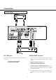
Connection CD, TAPE Jacks CD, TAPE jacks DIGITAL IN/OUT terminals Connect the component with RCA to RCA cords. Make sure to connect : If the CD player or tape player has digital outputs, connect the component with coaxial cables or optical cables. white plug to white jack(L:left) red plug to red jack(R:right) DIGITAL IN to DIGITAL OUT(CD, etc.) DIGITAL OUT to DIGITAL IN( MD, etc.) < Connect to any one of the DIGITAL IN terminals.
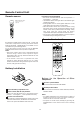
Remote Control Unit Precautions concerning batteries < Be sure to insert the batteries with correct positive "+ " and negative "_ " polarities. < Use batteries of the same type. Never use different types of batteries together. < Rechargeable and non-rechargeable batteries can be used. Refer to the precautions on their labels. < When the remote control unit is not to be used for a long time (more than a month), remove the batteries from the remote control unit to prevent them from leaking.
Basic Operations Basic Operations (1) 2 3 Basic Operations (2) 4 F A POWER STANDBY/ON Button Press this button to turn the power on. Press it again to turn the system off (power standby mode). The STANDBY indicator lights up in power standby mode and goes out when this unit is turned on. B SPEAKER Select Button With the unit in the STEREO mode, SPEAKERS A and B can be selected simultaneously.
Basic Operations Basic Operations (3) G Muting To mute the sound temporarily, press the MUTING button. Press the MUTING button again to restore the sound. If you change the volume during the muting, the muting will be canceled. While muting is engaged, the MUTING indicator will flicker. H I H PHONES jack G For private listening, insert optional (not included) headphones (1/4-inch plug) into the PHONES jack, and press the SPEAKER ON/OFF button to cut the sound from speakers.
Radio Reception Radio Reception (1) Radio Reception (2) 2 1 A FM MODE Button 3 4 Pressing this button alternates between Stereo mode and Mono mode. 1 Select the TUNER mode by turning the FUNCTION selector. Stereo FM stereo broadcasts are received in stereo and the STEREO indicator lights in the display. If FM broadcasts with weak signal strength are received, the FM muting function works automatically to cut the signals, eliminating loud noise.
Radio Reception 4 Radio Reception (3) 1 2 4 3 Preset Tuning This facility is used to store FM, AM broadcasting from Channel 1 to 30 respectively. Automatic Memory Prestting 4 A How to select preset stations 1 Select the TUNER mode by turning the FUNCTION selector. Press the PRESET buttons or the numeric key(s) of the remote control unit to select a preset channel. 2 Select the AM or FM by pressing the BAND selector B About MEMORY SCAN button. You can scan the preset stations by this function.
Radio Reception Manual Memory Presetting 1 Direct Tuning 2 FM: 100 kHz steps AM: 10 kHz steps Ex.: FM 107.5 MHz 3 4 6 5 6 1 Select the TUNER mode by turning the FUNCTION selector. 2 Select the AM or FM by pressing the BAND selector button. 3 Press the MODE(TUNING) button to change the tuning mode from preset to manual. The PRESET CH. indicator disappears from the display. 4 Select the frequency you want to preset by pressing the PRESET button. 5 Press the MEMORY button briefly. Ex.
Video Operations Playing Video Sources Tape dubbing Note: When playing videos that feature surround sound, refer to "Available Surround Modes". Tape Dubbing (from TV/VIDEO 2, AUX/VIDEO 3 or DVD/CD to VCR/VIDEO 1) 1 Select the VCR/VIDEO 1, TV/VIDEO 2, AUX/VIDEO 3 or 1 Turn the FUNCTION (source) selector to select the VIDEO DVD/CD mode by turning the FUNCTION selector. 2 Play the component corresponding to the FUNCTION selected.
Available Surround Modes The surround functions create a “live” atmosphere such as that experienced in movie theaters, discos, stadiums and concert halls. This unit is provided with the following surround modes. DTS (Digital Theater System) Select the appropriate surround mode according to the program source. < Note that surround speakers are needed for DTS/DOLBY DIGITAL/Dolby Pro Logic Surround mode to function, and a center speaker is needed for the 3 Stereo mode to function.
Available Surround Modes DOLBY DIGITAL Surround SURROUND MODE Button The Dolby Digital surround format lets you enjoy up to 5.1 channels of digital surround sound from a Dolby Digital program source. If you connect a DVD player or an LD player equipped with a DOLBY DIGITAL output to the U DIGITAL (Dolby Digital)/DTS/PCM DIGITAL IN jack on a surround mark, receiver/amplifier and play DVD or laser discs with you will experience even better soundquality, greater spatial accuracy, and improved dynamic range.
Available Surround Modes When playing recordings of live music, this mode provides a feeling similar to actually being in a concert hall. When this mode is selected, the normal program source is directed to the main speakers and a reverberated sound is directed to the surround speakers. This mode is suited to program sources which contain a large amount of reverberation. > DOLBY PRO LOGIC Surround > STADIUM Surround Use this mode when playing movie or music videos which carry the U DOLBY SURROUND mark.
Speaker Configuration FRONT SPEAKER Mode: < F-LARGE: The mode to choose if a large speaker is installed. Front channels output is full range. < F-SMALL: The mode to choose when using compact speakers. When using small compact front speakers, it is recommended to connect a powered subwoofer to play the LFE/Bass out channel. 1 Caution : If the subwoofer selector is set to off, the LFE/Bass out frequencies are sent to the front speakers.
Delay Time Delay Time The delay time can be individually set for the Dolby Digital/Dolby Pro Logic modes using the DELAY TIME (CENTER/REAR) buttons. When you adjust the delay time in the Dolby Digital mode, an additional 15 ms is automatically added to the surround channels in the Dolby Pro Logic mode. The current setting is shown on the display.
Test Tone Balancing relative volume between speakers The test tone function is useful to adjust the relative volume between speakers in DTS, DOLBY DIGITAL or DOLBY PRO LOGIC mode. Once the balance is set, you don't have to change the balance as long as the speakers aren't moved. 3 1 4 2 1 Press the TEST TONE button in DTS, Dolby Digital or Dolby PRO LOGIC mode. The test tone is emitted from each speaker in the following order at 2-second intervals.
TROUBLESHOOTING To determine any problem with your receiver, always check the most obvious possible causes first. If any problem still remains after your have checked the items below, consult your nearest TECHWOOD dealer. Problem Probable Cause Remedy Amplifier When listening to the music in stereo, left/right speakers sounds reversed. Speakers are connected wrong. After checking, if needed, reconnect. Low hum or buzzer sound. Power line of a fluorescent light is installed near this product.
Specifications Amplifier Section AM Tuner Section Stereo output Power F. T.C. Rating Tuning Range: 200 Watts total. 100 Watts RMS per channel minimun, one channels driven into 8 ohms from 20Hz to 20KHz with no more than 0.9% T.H.D 530 kHz – 1,720 kHz (10 kHz steps) Usable Sensitivity: 55 dB/m Total Harmonic Distortion: 0.8% at 85 dB/m Signal-to-Noise Ratio: 45 dB at 85 dB/m Surround Output Power (0.9 % THD, 1 kHz, 8 ohms): Video Section 500 Watts total.
WELTON U.S.A. 11625 COLUMBIA CENTER DR.